Coffee Capsule Color Detector
Most of us drink coffee. Some like it for its taste, others like the buzz, and many feel that they can't start the morning without it. In our office, the Nespresso coffee machine is a shrine. Every morning you can find a few zombies hovering over it, waiting for the caffeine to kick in. Since coffee capsules have come into our lives, there's such a large variety of flavors to choose from. But you know what? With all these options, sometimes it's hard to remember which color's which, and that's how we can up with the capsule color detector. In the tutorial we'll take you step by step through the process of making one. Ready?
The idea is pretty simple - you drop a capsule into the tube, and once it’s completely dark, a single LED lights up.
The RGB light sensor reads the brightness level of each color channel - Red, Green and Blue.
It then sends the values to the Arduino, which recognizes the capsule based on the pre-defined values in the code.
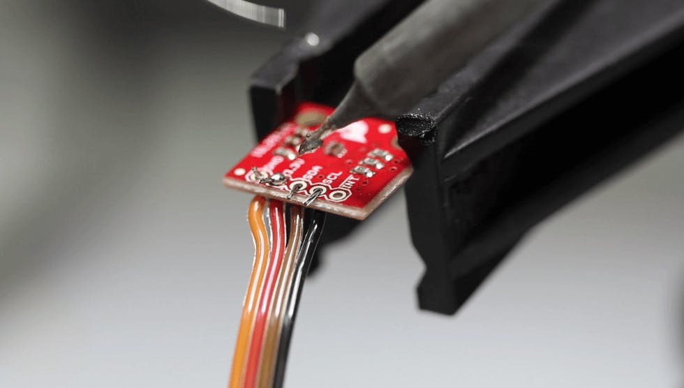
- RGB light sensor ISL29125
- Arduino pro mini 328- 5V/16MHz
- Wall Adapter Power Supply - 12VDC 600mA
- Serial Enabled 16x2 LCD

- 220Ohm Resistor
- Logic Level Converter - Bi-Directional
- Voltage Regulator 3.3v
- TO-220 HeatSink
- DC Barrel Jack Adapter
- Electrolytic Decoupling Capacitor - 10uF/25V
- SparkFun FTDI Basic Breakout - 5V
- Capacitor Ceramic 0.1uF
- Jumper Wires Standard 7" M/M
Click on this link or the diagram below, to see the circuit wiring on circuito.io

After you put together the circuit, download the test code from the "code" tab. The point of this code is to make sure that you got your wiring and components working properly.
Make sure to set the right port and the right board - Arduino pro mini 328- 5V/16MHz.
Once you have this set up, verify and upload the code, and test the different components using the serial monitor, as explained in the code.
If one of the components isn't working, you'll need to debug the circuit. First make sure that you got your wiring right. If that doesn't solve the problem, check that the components are OK, and if you have a spare, try to connect it to see if it's working. If it still doesn't work, check out our debugging post or ask for help on our forum.
After you see that everything is working properly, download the code from our Github repo.
Now you'll need to calibrate the RGB sensor:
1. Un-comment these line in the code by removing the /* and */ before and after the lines:
 /*
	Serial.print("Red:");
   	Serial.print(rgbSensor.readRed());
    	Serial.print("Green:");
    	Serial.print(rgbSensor.readGreen());
    	Serial.print("Blue:");
    	Serial.print(rgbSensor.readBlue());
    	Serial.println();
    	delay(500);
	*/
2. Upload the sketch to the Arduino
3. Open the Arduino IDE serial monitor and insert a capsule
4. Write down the RGB values that appear on your serial monitor
5. Type the 3 values under the correct capsule name in the capsule array code:
 int cosi[3] = {229, 389, 329};
	 int dulsao[3] = {142, 253, 191};
	 int roma[3] = {83, 196, 177};
	 int livanto[3] = {188, 299, 187};
	 int vivalto_lungo [3] = {134, 294, 449};
	 int bukeela_lungo[3] = {330, 452, 319};
	 int kazaar[3] = {60, 165, 180};
	 int volluto[3] = {263, 421, 248};
6. To add other capsules, you'll need the create a new capsule data array:
//new_capsule_name

    if (abs(red - new_capsule_name[0]) < thresh && abs(green - new_capsule_name[1]) < thresh && abs(blue - new_capsule_name[2]) < thresh ) {

    Serial.println("new_capsule_name");
      serlcd.setBrightness(28);
      serlcd.clear();
      serlcd.selectLine(1);
      serlcd.print("new_capsule_name");
      serlcd.selectLine(2);
      serlcd.print("Intensity: 10/10");
      delay(2500);
      serlcd.clear();
      serlcd.selectLine(1);
      serlcd.print("Cup Size:ml");
      serlcd.selectLine(2);
      serlcd.print("flavor");
      delay(2500);
      serlcd.clear();
}
Now for making the body of the capsule color detector, we 3d printed 2 parts, that we put on Sketchfab for you.
We printed it using black PLA, using our Flashforge Creator Pro 3D Printer.
It’s important to use black filament otherwise light will get into the capsule reader and can affect the RGB sensor readings.
Another option if you don’t have black filament is to spray the inside capsule cylinder with black spray-paint.
The final step, after making sure that everything is working properly on the breadboard, is to solder the components onto a permanent perforated breadboard to save space and make the wiring more durable.
We're planning to make this project more compact and also add a speaker to call out the name of the capsule that was detected, which can be useful for blind or visually impaired individuals.
Another option is to take the color coding method to other uses rather than identifying the Nespresso capsule color.
--
This wraps up the capsule color reader project. Is was great fun to build this project, and we're sure you'll enjoy it as well. If you need any help, you're welcome to write on our forum and we'll do our best to help. You're also more than welcome to share pics and videos of the making process with us.