How To Build a Light Painting Line Follower
Welcome to our most recent creation - the Light Painting Line Follower!
We are very excited to be launching this project - first of all since it’s the first full project overview on our Blog! And second, because we’ve been dreaming about this project for a long time and we were finally able to make it happen! Just to clarify, we’ll still be posting our project tutorials on our community hub on Hackster. In the blog, we’ll have more in-depth information about the project such as information about the components we used and how they are implemented in circuito, the code logic, and other interesting factors about the project.
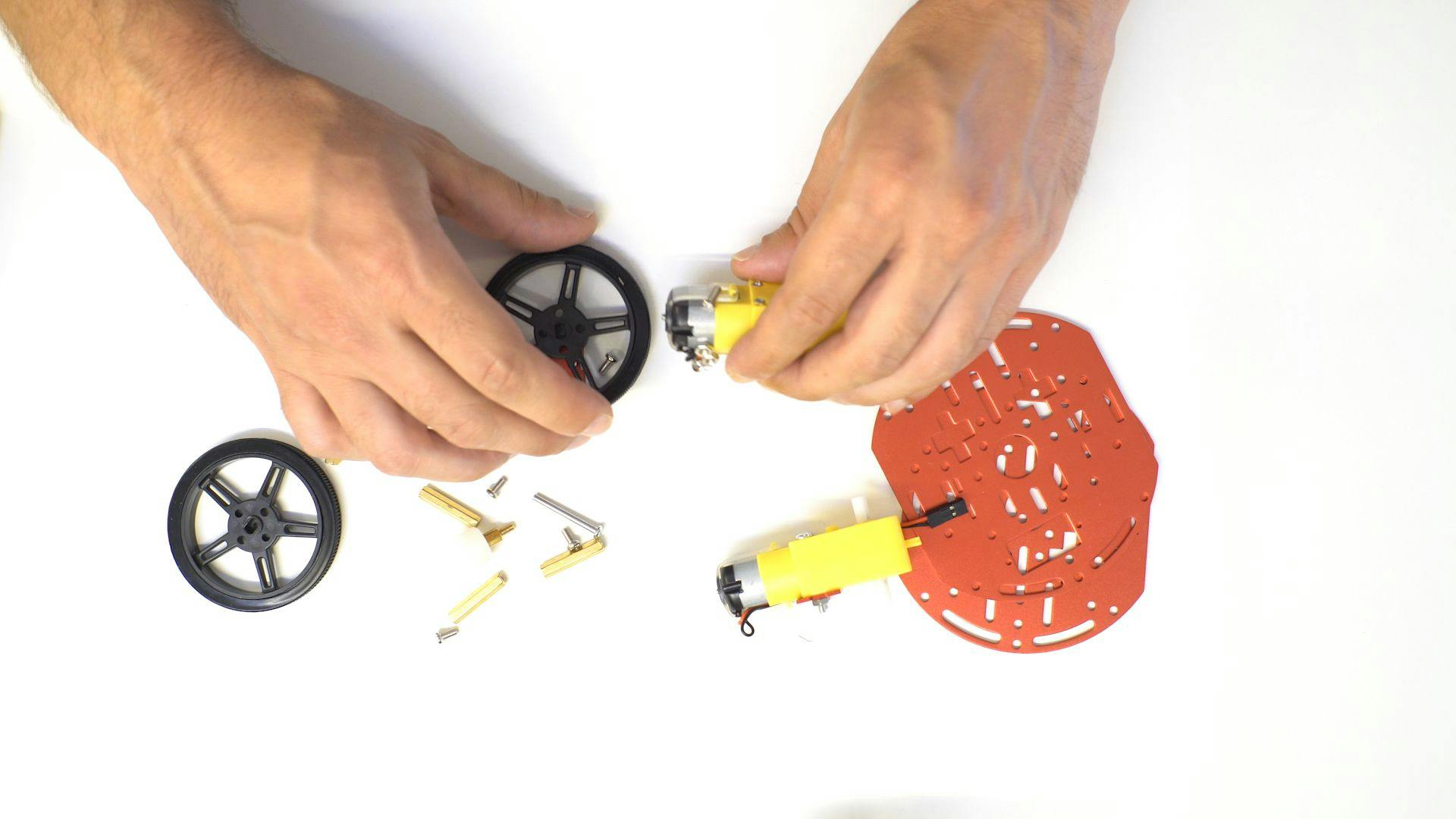
We went with the Mini Round Robot Chassis Kit by Adafruit for the body of the line follower.
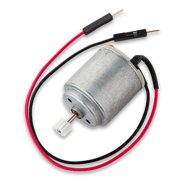
This kit has 2 wheels with DC motors, an anodized aluminum frame, and a plastic caster ball. It’s great for basic robotic projects because it’s easy to assemble and the differential drive, meaning the two wheels are controlled separately, gives it a nice smooth turning ability. Another plus for this kit is that it elegantly fits the power supply, Arduino and the rest of the electronics.
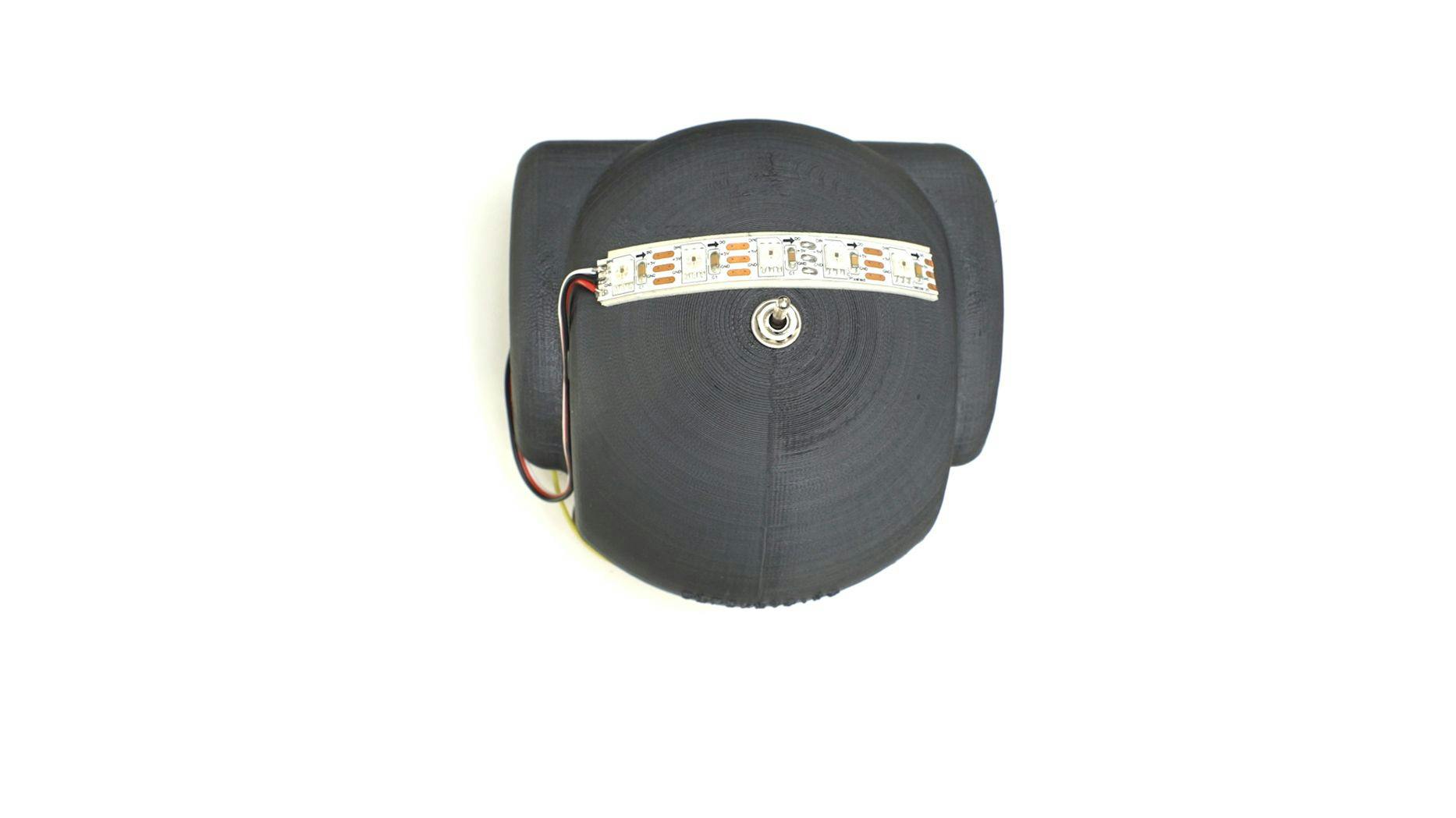
We also decided to make a 3d printed plastic hood for the line follower, for which we used a Flash Forge Creator pro, 0.3 res. On top of the hood, we placed 5 addressable LEDs with which we’ll make the light painting.
The Arduino pro mini 5v is our preferred choice for this project. It’s connected to two dc motors through the L298 driver. The driver acts as a hub between the motor and the Arduino. It is connected directly to the power supply, and it transfers the high voltage of the power supply to the motors corresponding to the Arduino low voltage control signals. The use of a dc motor driver gives control over the speed and direction of the motor.
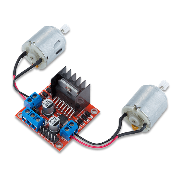
It is also possible to use the DC motor with a standard transistortransistor instead of a driver, but you’ll only be able to control the speed and not the direction of the line follower. In any case, you can find both options on circuito.io.
IR line followers
One of the reasons we had to wait for so long before posting this project, is because we didn’t have the IR line follower component on circuito.io till recently.
The line follower has an IR transmitter and an IR receiver and it detects reflections of light. If there is less reflection of light, it assumes that there is an object or a dark color that absorbs the light. On the other hand, if the reflections that are returned are more powerful, this means that there is nothing blocking the way.
The IR line follower has a digital output pin, therefore, the outputs are binary - either 0 or 1:
0 = light was not reflected back (there is a dark color or object absorbing the light)
1 = light was reflected back, there is nothing in the way to absorb it.
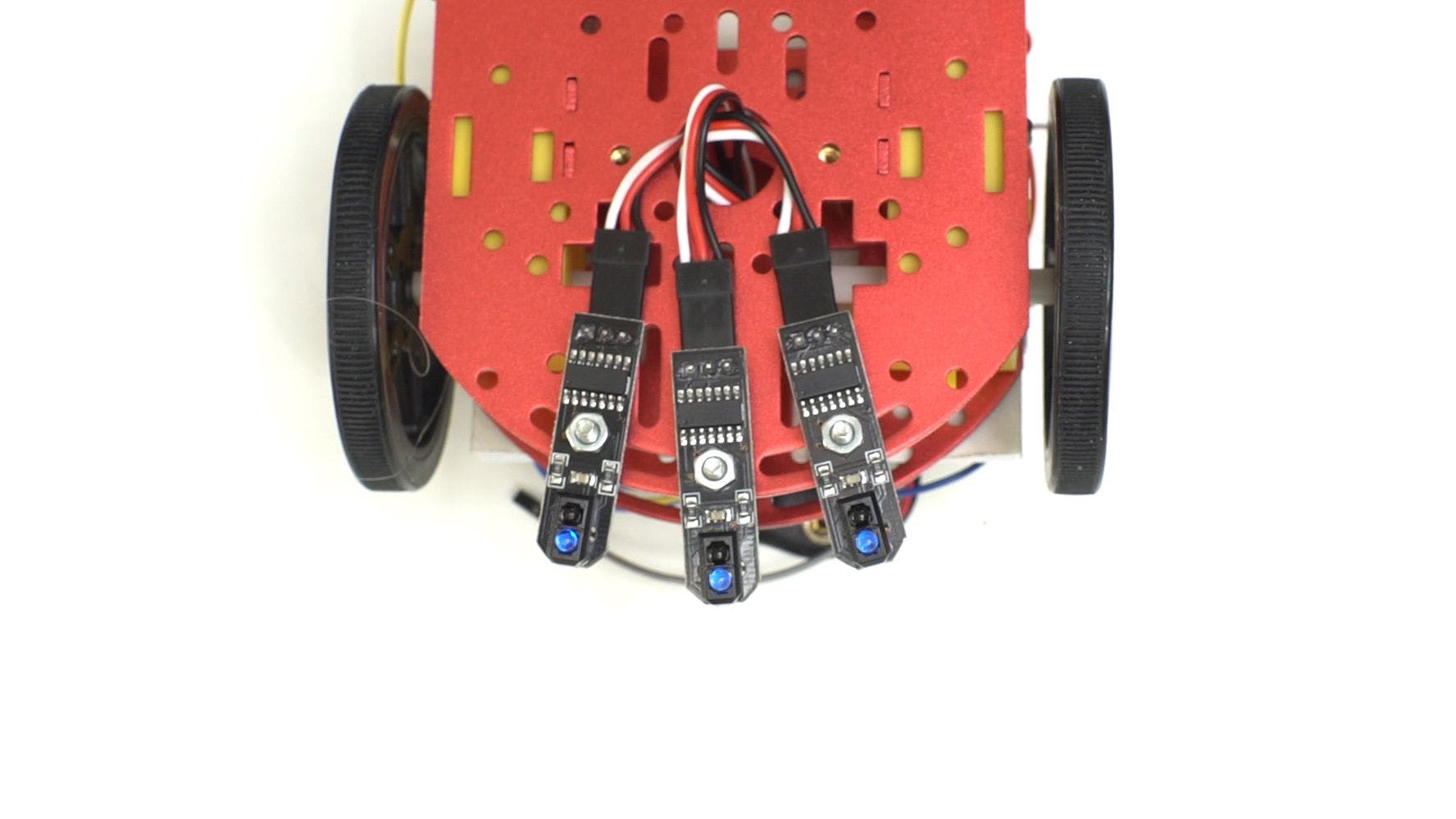
Our robot has 3 IR line following sensors. Why you ask?
The middle sensor recognizes the line itself, while the two others recognize if there needs to be a fix in position or direction. This actually creates 8 combinations which are then decoded and translated into the movement of the motors and wheels.
Ready to follow the line? Make your own line follower >>
In the mainloop function you can see that there is an “if” statement:
if (irLineFollow1Var && !irLineFollow2Var && irLineFollow3Var)
There are 3 variables in this statement that represent each one of the line followers.
Let’s refer to them as the 1 (not black) and 0 (black) from before.
The ‘!’ means “NOT” so it turns 0 into 1 and vice versa.
Let’s go back to the first statement:
Var1= 1 , Var2= NOT(0) = 1 Var3= 1 the ‘&’ sign between the vars means AND (Boolean).
Therefore, if we perform the AND operator: 1&1&1 = 1 which is “true”. This means that the first “if” statement condition has been met and the line follower will continue to go straight ahead.
you’ll see a few “else if” statements. This means that if the first statement came out “False”” it will go on to the second, third and so on. You can read more about how to program your line follower on this great tutorial.
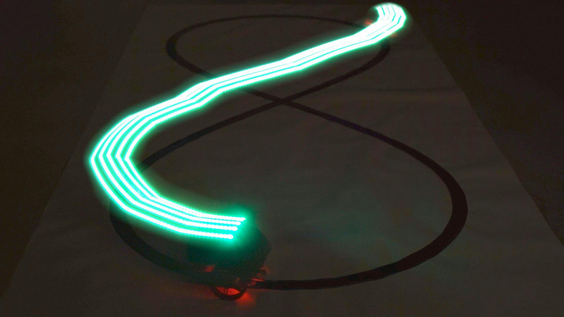
I think this is the real reason we’re so excited for this project! Light painting is a photographic technique in which exposures are made by moving a hand-held light source while taking a long exposure photograph, either to illuminate a subject or to shine a point of light directly at the camera, or by moving the camera itself during exposure. Since the line follower is already in motion, all we had to do was place the LEDs on top of it, and film it in a certain way, as it magically draws the Arduino infinity icon. I’ll fill you in on a little secret, it wasn’t as easy as I draw it out to be, but the result is pretty awesome.
Time to start working! Click here to see the step by step guide on circuito.io >>
So our first project post is coming to an end. We’d love to hear your comments and ideas about the project and about the post. You are more than welcome to share your thoughts here or shoot us an email. Till next time!