How to Make an Interactive Cat Laser Pointer
It’s been quite a while since our last project because we’ve been busy releasing circuito.io 3.0 (check it out!). When we finally sat down to think about what to make, we concluded that we’ve made a few projects for dogs, but none for cats, And that’s just wrong! From there, it didn’t take long until the cat laser pointer was underway. It’s a perfect mix of playfulness and laziness, just the way we like it.
So what did we do?
We made an interactive cat laser game that's controlled via mobile, and also has an automatic mode. We used a pan-tilt unit we found online (info and credit later on in this post), adjusted it to fit the laser diode, connected it to our phone with a Bluetooth module and started playing around with Pepper the cat, who turned out to be quite the Flamenco dancer.
On a side note - we read in various places that laser toys are not a replacement for physical cat toys, but you can combine the two, and use the cat laser to point at physical toys that the cat can play with. We’re not experts on the subject, so just use your common sense and we’re sure you’ll figure out what’s best for your cat.
Primary Components
Secondary Components
Pan-Tilt Mechanism
We started off by looking for an affordable pan-tilt mechanism. We found this model on Thingiverse (credit to Fernando Bueno from 3D Open Hardware) and it was a good starting point.
The mechanism has three parts. We remodeled the top part of the servo and added a small dome with a hole so that the laser diode could fit in it. The other two parts we printed as is. You can find the printable files on Thingiverse.
The steps below explain exactly how to put together the pan-tilt and the electronics:
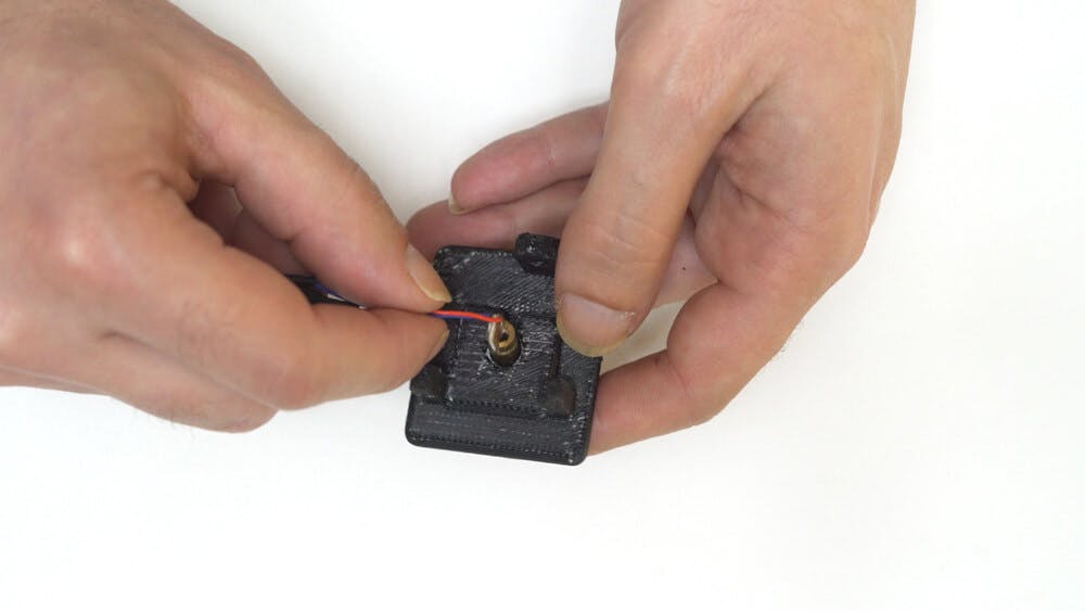
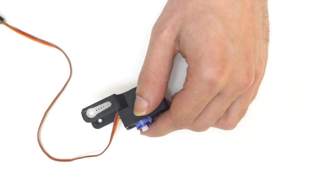
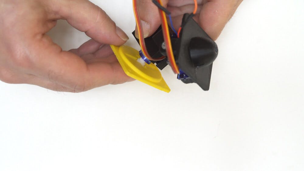
Step 1: Insert the laser diode into its hole in the top plastic part. You may need to solder longer wires to the diode. Note: Home 3d printers tend to be inaccurate, so if the laser doesn’t fit into the hole, you can use a 6mm drill manually to expand it. Just make sure that you don’t drill all the way because the tip is a bit more narrow to prevent the laser from popping out of its place.
Step 2: Place the servo so that its ribs interface those of the top plastic part.
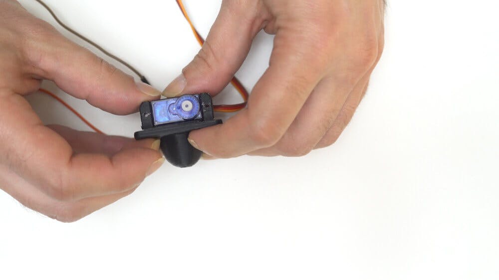
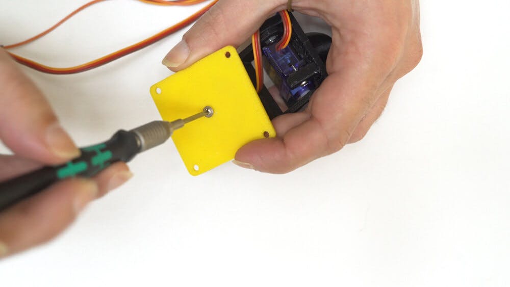
Step 3: Use two M2 Sheet Metal Screws to keep the servo in place. Make sure that the servo doesn’t crush the laser wires, and the wires are placed in the tunnel underneath it.
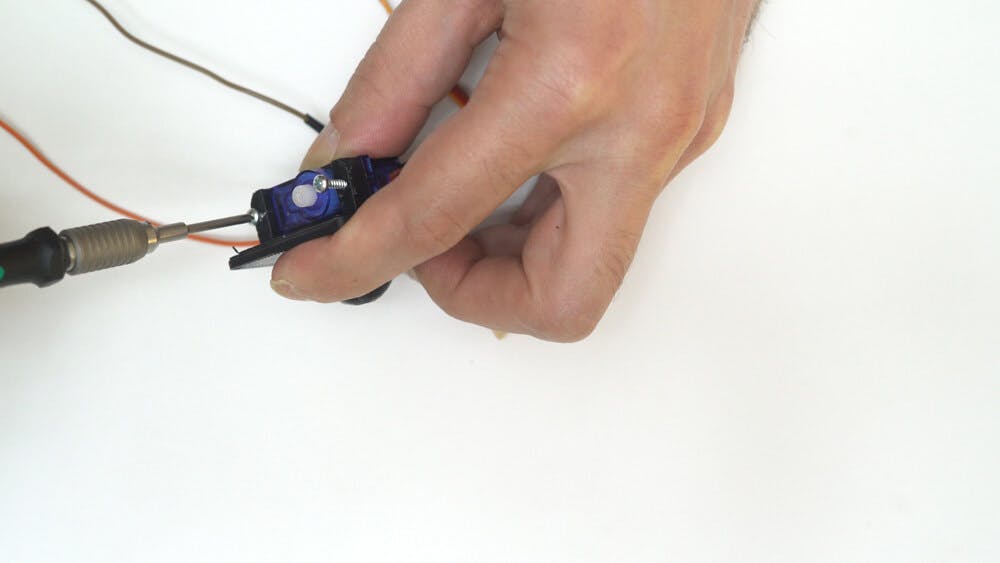
Step 4: Place the second servo inside the middle plastic part. Insert the wires through the niche, this can be a bit difficult because the servo needs to sit pretty tight. We used a screwdriver to force it in.
Step 5: Place one servo horn in the niche
Step 6: And an M3 nut in the niche on the opposite arm. Connect the middle and top plastic parts
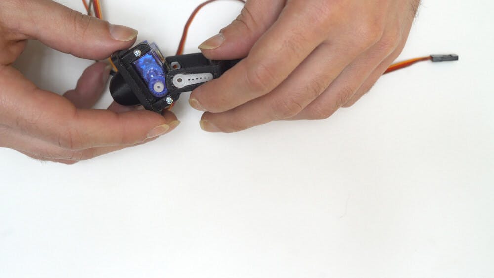
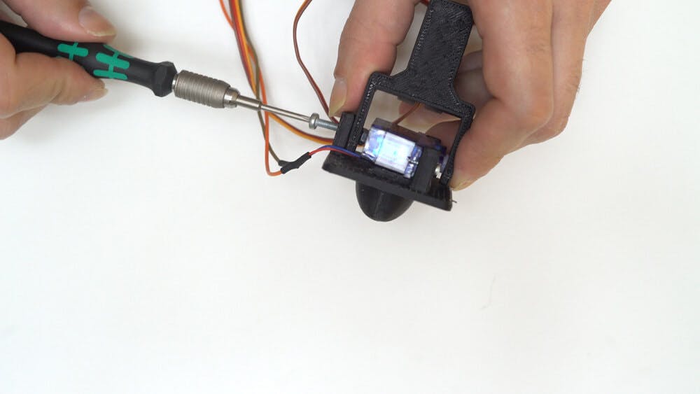
Step 7: Connect the Servo horn to the servo head, and from the other side screw the M3 bolt into the nut. At this point you need to check the servo movement range manually by moving it from side to side. It’s important to do this because if the range is limited the servo might get stuck (you can see how we did this in the video). After adjusting the range, place the servo horn screws in between the servo horns and the servo.
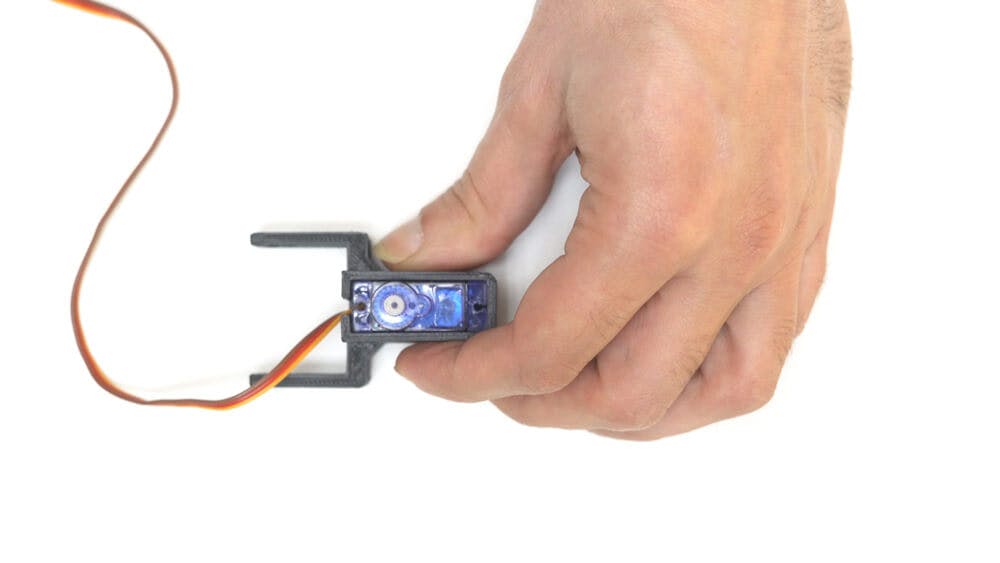
Step 8: Moving on to the base - place the servo horn into the niche
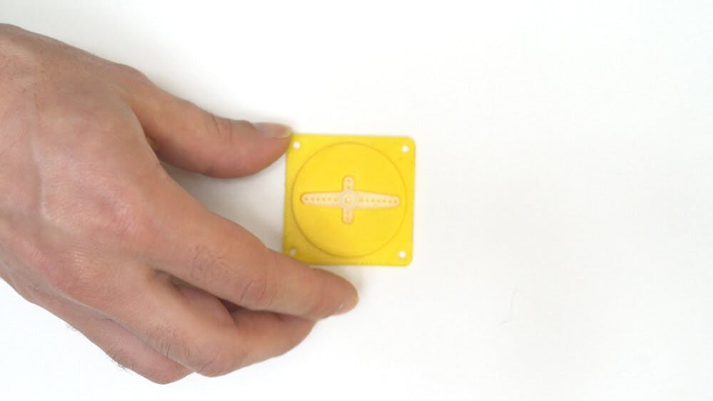
Step 9: Place the servo head into the servo horn and check the servo movement range like you did before.
Step 10: Once the range is right, insert the servo horn screws between the servo horns and the servo, from underneath the plate.
We decided to use two small servo motors because they are relatively cheap and have no problem carrying the weight of the laser (which is pretty light).
We chose a simple laser diode and a Bluetooth HC-05 connectivity device so we can control the laser from my phone. Unfortunately, it only works for Android (sorry iPhone users).
Here’s a link to the circuit wiring instructions
After you wire the circuit, use the test code in the project guide, to check that it’s wired correctly.
The code from circuito.io uses the built-in servo library of the Arduino IDE, but it doesn’t provide the behavior we want for this project. Therefore, I’ve replaced it with “VarSpeedServo” library. This library adds a smoother movement to the servos, giving the cat time to respond and play.
You can also find it on our GitHub repo of this project.
Download the source files. Only edit pin numbers from the original code from circuito.io.
To connect to the unit wirelessly, we used HC-05 Bluetooth module and paired it with the ‘Arduino BlueControl’ app. You can find it for free on Google Play Store.
How to Configure the Arduino BlueControl app
The Cat Laser has two Modes:
More Buttons:
After everything was in place, we wanted to make the circuit a bit more durable, so we decided to make an Arduino Shield using Sparkfun’s Proto Shield.
we moved the parts from the breadboard to the Proto Shield and soldered them the same way they were wired on the breadboard.
we used 6 female headers instead of soldering, to connect the Bluetooth module to the Arduino so we can plug and unplug it easily.
we also used two 3-pin male headers for easily plugging the laser.
Before the final assembly, we checked that the new circuit with the Proto Shield was working and placed the pan-tilt unit on the edge of the wiring box.
And that's how we built the cat laser pointer! We're glad to have shared this project with you and hope you have as much fun making it as we did. You're welcome to share the results in the comments below. Also, if you have any questions or ideas, we'd love to hear those as well.
Enjoy Making!