How to Use a Breadboard [with Q&A]
If you’ve worked on electronic projects in the past, you've probably heard and perhaps even used breadboards before. But what does 'breadboard' mean? Breadboards can be a bit confusing at first if you don't understand the logic behind them - which is exactly why we came up with this guide to getting started with your breadboard. We are going to briefly explain how breadboards are built and how they function, how to connect components to the breadboard, where they get power supply from, which types of breadboards there are, and how to use a breadboard with your circuito.io project. We also added a cute little project you can build based on a breadboard!

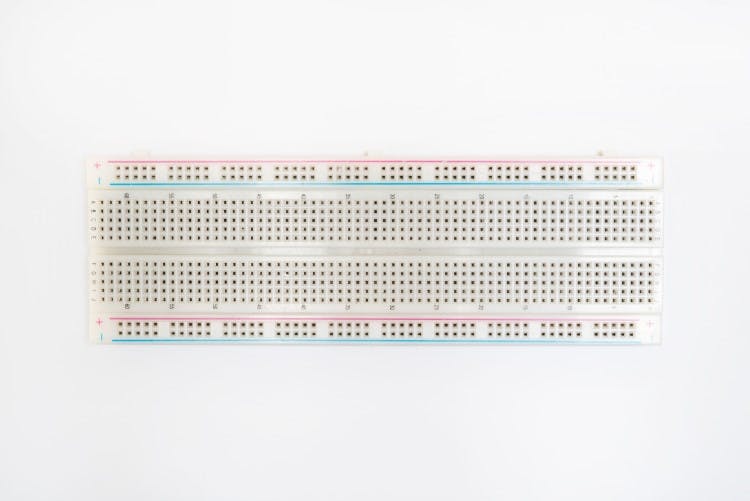
A breadboard is a rectangular board with many mounting holes. They are used for creating electrical connections between electronic components and single board computers or microcontrollers such as Arduino and Raspberry Pi. The connections aren’t permanent and they can be removed and placed again. In fact, you can even replace components to customize your project or work on a completely different one, using the same breadboard.
The vertical columns of the breadboard are called terminals, while the horizontal long rows are called power rails because they are mostly used to connect the power supply to the breadboard. The positive rails are indicated by red lines, while the negative rails are indicated by black ones.
Breadboards are used to help you connect components to complete your basic circuit. The reason it's called breadboard dates back to when electronics components were much bigger and people would actually use wooden breadboards (boards used to cut bread) to connect electronic circuits. Fortunately, things have changed since then and only the name has been retained.
Breadboards are sold separately by most electronics distributors, and they also appear in most of the basic electronics kits you'll buy.
A breadboard connection with an electronic component is made with the help of leg-like structures made of metal. These are called “leads”, and they can vary in size. The shorter ones are often referred to as pins. So, if your electronic component has leads, it can be connected directly to the breadboard. DIP-based (that's dual inline package) integrated circuits are built to fit perfectly into a breadboard, with each pin fitting over a breadboard hole.
These leads can be pushed into the holes that are designed to hold them in place and prevent them from getting loose or falling out of the breadboard. You can even turn the breadboard upside down and these connections wouldn’t come off. They are tight enough to insert and remove, but, not enough for breadboard connections to come off on their own.
The tightness comes from the fact that breadboards have small metal clips hidden under these holes, which hold everything in place. They basically grab onto the leads that you insert. Other than that, breadboards usually have a backing layer as well, to hold the clips themselves in place. This backing layer is normally made of a double-sided tape. One side of the tape is usually covered to prevent the sticky layer from being exposed.
However, if the breadboard needs to be attached to your electronic project, you can peel this cover off and use the other sticky side. The next thing you’ll notice on a breadboard are the markings such as letters, numbers, and symbols. The way these markings are laid out may vary from breadboard to breadboard. But, the purpose is all the same. These markings help users locate the exact holes they need to connect the components to. The closest example of this would be an Excel spreadsheet. You have cells, rows, and columns. The row number and the respective column letter tell you which cell you need to be looking at. It’s almost the same with breadboards.
For example, C12 refers to the breadboard hole under column C and in row 12.
There are plenty of ways to supply power to a breadboard. For starters, you can always borrow power from development boards such as Arduino or Raspberry Pi. Arduino boards come with female headers from which power can be sourced. You have a range of pins for ground and power that can be connected to a breadboard’s power rows. The Arduino board itself receives power from an external power source that is connected to the circuit. This could be a battery or even a wall unit.
Apart from that, you have binding posts on certain breadboards. These posts first need to be connected to the board using jumper cables and then, you connect wires to the binding posts. Other than that, you have breadboard power supply options such as benchtop power supply and special power supply units built exclusively for breadboards. These units usually come as part of a breadboard kit. Some of them let you draw power directly from a wall unit or through your computer via the USB port.
One of the commonly used breadboard power supply modules is a circuit board that is connected to the top of a breadboard. This module provides power via the breadboard’s power rails. These modules can be either in 3.3 V or 5 V fixed dual output regulated configurations. There are a few that come with variable power supplies as well. This can be helpful if you need over 5 V.
Now that you have a basic idea of a breadboard, the next step is to actually learn how to use it. The way breadboards are used can vary based on the specific project you are working on. So, to give you a practical example of how a breadboard works, we’re going to us a minor circuit as an example. For this circuit, we will be using a LED, AA or AAA battery pack with black and red leads, a push button, a 100ohm resistor, and, of course, a breadboard. You will use these components, including the breadboard, to create a working electronic circuit. The first step is to connect the red lead in the battery pack to the breadboard’s power bus. Then, you connect the black lead to the ground bus. The third step is to connect the resistor from B12 to the ground bus.
As for the push button, the four pins need to go into holes E10, F10, E12, and F12, respectively. Finally, the LED’s short lead into the J10 hole and the long LED into the power bus. Your basic LED circuit is now ready. You can use this diagram to get a clear idea of how to create the circuit. You can also refer to this image. Of course, you don’t have to follow the diagram exactly as it is. You can make changes as long the circuit is “electrically equivalent”. What that means is the electricity has to flow through a closed circuit, which is what will allow it to function as intended.
Today’s breadboards are made from all sorts of materials and they vary in size and shape as well. Larger breadboards are great for prototyping complex projects; mini breadboards are suited to smaller ones.
However, if you were to divide breadboards into broader categories, you would end up with two key types of breadboards – solderless and soldered. Solderless breadboards are what we have been discussing so far and they are the best option, especially when you’re a beginner. They are called “solderless” because there is no soldering required to create connections or to hold things in place. For those who are wondering what soldering is- it’s a method of connecting electronic components together by melting a metal known as solder. The melted solder conducts electricity, which helps create the circuit and it fuses with the connected ends to hold the connection together.
Which brings us to the topic of soldered breadboards. These are breadboards where the connections are soldered. There are no metal clips to hold the leads. Soldered breadboards are rarely used. In fact, soldering is mostly done on PCBs or Printed Circuit Boards. Before that happens, engineers or technicians will actually use a solderless breadboard for prototyping. They move onto a soldered PCB only if the prototype is a success. So, these are the two main breadboards you are likely to come across.
Hopefully, you’ve developed a rough idea of what a breadboard is and that’s great. But you probably have a few questions still hovering around in your head, for example, what are the applications of breadboards in circuito.io?
So, we’ve created a list of FAQs that we normally receive from our users. The answers to these FAQs will hopefully make it much easier for you to use a breadboard in conjunction with the projects on circuito.io.
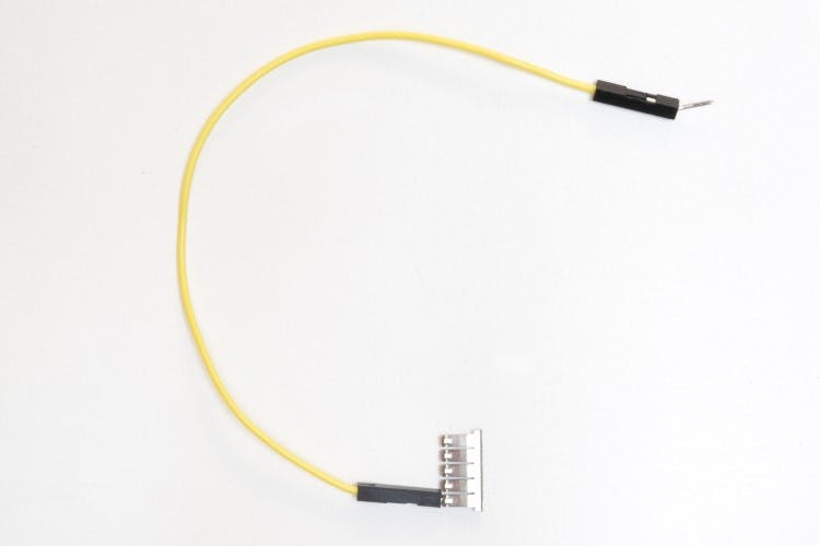
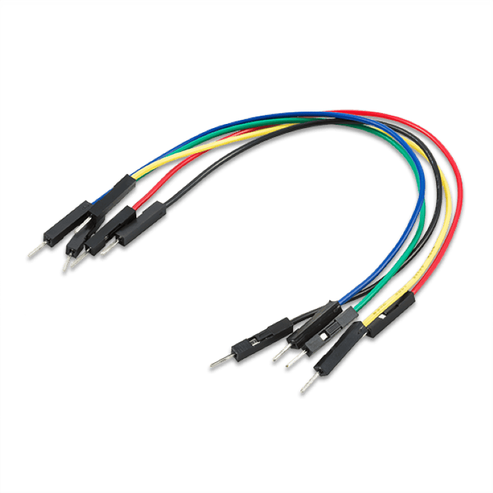
The simple answer to this question is "no". Jumper wires are all the same. However, for the sake of avoiding confusion, it is recommended that you use one set of the same color wires for “+” connections and one set of another color for “-“ connections.
In fact, it’s even better if you use red wires for “+” connections and blue or black for “-“connections.
Again, no. The hole doesn’t matter as long as you are using one that’s on the same power rail or terminal strip. This is because the power rails are linked to each other and so are the terminal strips. So, the current flow and the conductivity are maintained within a specific strip.
However, if you were to skip to another terminal strip or power rail, then you would see a problem with your connection.
No. The horizontal rails function in much the same way. They are all connected and used to connect the positives and the negatives. However, do note that the power rails on both sides of the breadboard aren’t connected. So, if you have to use both those power rails, you have to make sure both of them are connected to the main breadboard power supply (and therefore to one another).
No. This isn’t possible. However, in some replies from circuito.io you may see two jumper wires being connected to the same hole. If you come across such diagrams, don’t worry. The solution is quite simple: all you have to do is connect the wires to different holes within the same row.
This isn’t a problem to worry about. You can always use a bigger breadboard or two breadboards together. In fact, most modern breadboards come with notches or tabs that allow you to connect another breadboard. You can actually use multiple breadboards this way, using a pair of red and black jumper wires to connect the positive and negative rails.
As we mentioned earlier, breadboards are used to create prototype circuits. Once you test a prototype and it proves to be successful, the next step is to go ahead with creating a PCB (Printed Circuit Board). Breadboards are temporary and they will always be subject to disconnection, which isn’t helpful if you’re going to construct a device that needs the connections to remain undisturbed. This is where PCBs come in handy. The connections in a PCB are soldered and therefore permanent. Breadboards are used mainly as a planning tool before manufacturing PCBs. They allow you to test the basic layout of your electronic circuit and tell you where a certain component needs to be placed and how it needs to be connected.
You can use Fritzing Fab to do this. Fritzing Fab is an online tool that allows you to create actual PCBs based on your fritzing sketches. PCBs are quite complex and the kind of people who work on them are usually electricians and other experienced individuals who have been working on circuits for a long time. One of the most popular tools used to design PCBs is Eagle. You can access more tools via our about online tools for makers and scroll to the PCB Design section. There is also this article for additional help.
The running breadboard is a simple project we made that uses a breadboard as an integral part of the design. The components for this build can be found on our Hackster Project Hub.
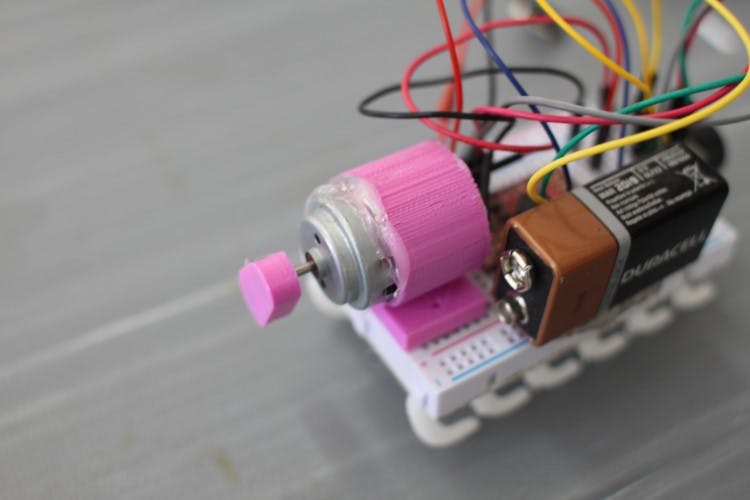
Once you have all the components, the next step is to create a basic circuit. To do that, you will first need the Arduino Pro Mini 328 board. On the input end of this board, you will need to connect the SparkFun Ultrasonic Range Finder - LV-MaxSonar-EZ1. On the output end, you will have to connect the SparkFun DC Hobby Motor. The circuit itself will be powered by a 9V Alkaline Battery.
The final circuit is then arranged and connected to the breadboard using the remaining components. To get a good idea of what the circuit should look like, click this link.
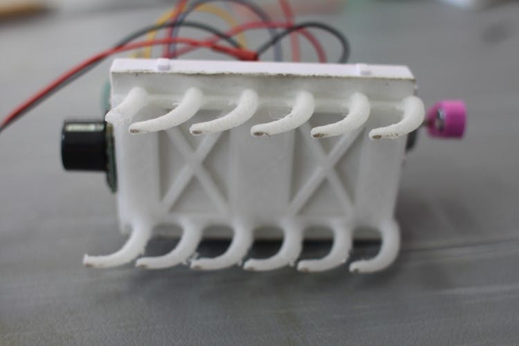
There are also parts that need to be 3D printed in order to complete this build. You can download the .stl files for those parts and find more details on our Hackster project hub.
Another thing to remember here is that you can to test your circuit using test code. The test code can be accessed by clicking the previously provided circuito.io link. Clicking this link will take you to a page where the circuito.io tool shows you how the circuit needs to be generated. Below, you will notice a button that says “Generate”. Click that button. Once you do that, you will be lead to a “step-by-step” guide. This guide provides each and every step that goes into setting up the circuit in detail. Towards the end, you will notice a section that says “code”. This is where you can download the test code.
Once you download the test code, upload it to the Arduino boards and carry out the test. If all goes well, the next step is to use the modified code, which can be accessed here. And you made yourself a running breadboard!
We hope you found this guide helpful and you now have a better understanding of what breadboards are and how to use them. As we mentioned earlier, breadboards aren’t complex devices. They might be a bit confusing at first, but, they are far from complicated. All you need to do is learn about them and things become super easy after that.
We invite you to take the information in this guide and, get a basic electronics kit, and start building your own project since that’s the best way to learn (in our opinion of course). Take the time to get to know about breadboards by incorporating them into your electronic circuit projects. Or, look for projects that require extensive use of breadboards. Breadboards are an incredibly useful prototyping tool, and the more you use them, the more you'll get from them!