10 Arduino projects for beginners anyone can make
Building Arduino projects can give you a great sense of satisfaction, but many times beginners aren’t sure where to start. There are lots of things to take into consideration when starting a project, and if you have no Maker experience, it can be quite confusing. For this reason, we put together 10 Arduino projects for beginners that anyone can make!

To get you started, it's best if you have an Arduino starter kit that contains: An Arduino, jumper wires, resistors, a breadboard, LED and buttons. Some of the projects require additional parts, and have links to where you can buy them.
In all the projects you’ll see below, we used circuito.io for the BoM (bill of materials), step-by-step wiring guide and code samples but of course you can change the original design, add or remove components and make your own version of the project.
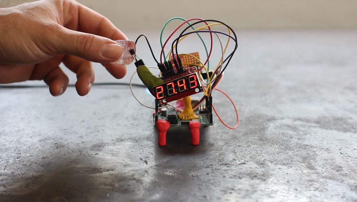
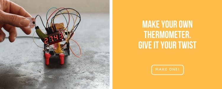
For your first project, we decided to show you how to make a thermometer. This is a rather simple build and it's one of those things that are just good to have around the house. Also for this project, we didn't 3d print any parts, and used minimum parts so that it's truly easy and self-explanatory.
The components you’ll need for this project are: Arduino Uno, DS18B20 - One Wire Digital Temperature Sensor and 7-Segment Serial Display.
When you have all the components you can start wiring them together. This project only has one input - temperature sensor, and one output - 7-segment display, so the wiring is not all that difficult. When clicking this link and you'll be redirected to our app, where the components for the project are already selected for you.
Let's take a look at the different components in a bit more detail:
Next thing we'll take a look at is the breadboard. In the wiring diagram on circuito.io you can see that we use a breadboard. Breadboards are a basic prototyping tool that allows you to test different wirings without needing to solder the parts together. This saves up a lot of time and material. Once you have the final design, you can create a PCB or use a perforated prototyping board, like the one you see in the picture above. We'll cover more about this issue in one of our future posts about different breadboards and prototyping boards. For this project you can stick with the breadboard if you want. Wow, we've already covered so much information! This may seem like a lot, and it really is, but that's why we're taking you into this world step by step, so don't give up if you don't understand everything quite yet. That's part of the fun - learning while you make things!
After the wiring is complete, we can take a look at the code. The code is basically a set of rules and instructions that tell your sensors and actuators what to do. If you want to understand a bit more about it, go over to our Arduino code blog post. You can watch this 3 video series about programming for Arduino by ILTMS.
Going back to our project, we'll just explain the basic logic behind the code here - the data read from the DS18B20 temperature sensor is presented on the serial 7-segment display using the sevenSegment.write and the ds18b20.readTempC() functions. The specific code for this project is found on our Hackster project hub in the code section at the bottom.
You need to download this code and paste it into the firmware tab of your original code, as explained in the tutorial on Hackster.
To put all the parts of this project together, we used a special material that we really like. It's called Sugru and it's this colorful and super-strong epoxy that you can mold to the shape you want and let dry. Once dry, this material is super-strong yet flexible, so it has a nice feeling to it and it's colorful and fun. Now that wasn't too bad right?
We made this project for St. Patrick's Day when we decided to test out our team's chugging skills. It was a day to remember (or maybe not). Apparently what we thought was a great score, we later learned was very slow in compared to people's reactions. Oh well, there's always next year, right?
Back to the build - the components we used in this project are Arduino Uno, FSR (Force Sensing Resistor), Pushbutton, Piezo Speaker and 7-Segment display. We used the same Serial 7 segment display as the one used in the thermometer, but this time instead of showing the temperature it displays the time that passed since the pint left the coaster. We can understand from this that the 7-segment is only a display element, and the actual computing is done in the code and processed through the Arduino.
Another component in this build is the force sensor which detects the weight of the pint on the coaster. Once it’s removed, the sensor detects the change in weight and starts the time, which is displayed on the 7-segment. The counter stops when it detects the weight of the pint back on the coaster. This action triggers another component - the piezo speaker, to play a tune. The pushbutton resets the time. These are all the components that comprise this project.
If you've completed the first project, the process here is pretty much the same: we made a special link for this project so that all of the components are already pre-selected. Following the wiring guide and after you've tested the code, you can complete the project and learn more about it in this post.

This next project we're going to introduce you to a new sensor. It's called MQ7 and it collects data about CO concentrations in the air. This sensor is highly sensitive and has a fast response rate. You can read about how it works on Sparkfun. The MQ7 gives an analog output, therefore, we'll connect it to the analog pin of the Arduino. The MQ7, like other gas sensors, requires a breakout board, which is basically an adaptor that allows you to connect the odly-spaced pins of the gas sensors to the breadboard.
So now that we know a bit more about gas sensors and how they work, we can move on to discussing the code of this project. Now that you already have two projects behind you, we hope that code doesn't look all that intimidating anymore, and we can move on to discussing what the code actually holds. So in this project, we'll meet the map function. This is a very useful and widely used function in different Arduino projects. As the name suggests, this function re-maps numbers from one range to another. In this case from the range of the MQ7 sensor, to the range of the RGB LED, which is 0-255. So as you may have guessed already (or seen in the video) the LEDs color will change from red to green according to the concentration levels of CO in the air. All the details about how to build this project, and more details about it can be found on the project's post on our blog.

The Thirsty Flamingo is another great Arduino project to start your making journey with. In this project, we'll use a soil moisture sensor to monitor our plants' environment. The soil moisture sensor is another analog sensor, like the MQ7. The large pads act as probes for the sensor and it actually behaves as a variable resistor. Therefore, the more water there is in the soil, the better the conductivity is between the two pads. This results in lower resistance, which means a higher SIG out. So actually, when there is more water, there are higher output signals which are then sent through the analog pin to the Arduino. The Piezo speaker we used here, which you've already met in the Chug Meter, is programmed to beep when there are high measurements from the soil moisture sensor.
We used a few electronics terms in this explanation such as: resistor, resistance and conductivity. If these words sound like gibberish to you at this stage, it's quite normal. We'll also be discussing some basic terms in one of our future posts, but in the meantime, you can start by taking this electronics class on Instructables. It's very informative, and has great explanations and examples. Start slowly, learn the basic terms, don't try to gulp it up all at once. It's just like learning a new language, it takes time and practice.
Going back to our friendly pink flamingo, after we've discussed how the soil moisture sensor works, and why the piezo speaker beeps when it does, we have a few more things to look at in this project. Mainly, the casing we built for it. This is the first project we'll be discussing 3D printing. While it is not necessary in this project to make the casing for the project, it does give it a nice and unique look, and in this case it also protects the electronics from getting wet (after all, you are planning on watering your plants at some point, right?).
Designing in 3D requires some experience and also a fair bit of creativity. Like with electronics, you can make 3D print other people's free designs without deeply understanding everything there is to know about 3D design. However, you'll probably want to pick up some information along the way and start creating your own designs at some point, or at least customizing other's designs to fit your needs and desires. A great place to start learning about 3D design is again through Instructables' classes.
In any case, for the thirsty flamingo, we made this cool cover that holds all the electronics parts really nice and tight, and you have only the "legs", which are actually the pads of the soil moisture sensor sticking out. You can find more information about how we built this project, the code and the 3d files in the designated blog post.

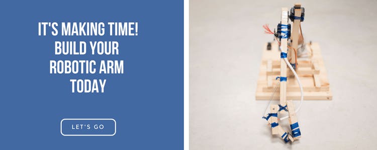
Robotic arms are quite a popular project in the maker world. There are different kits for building robotic arms, and many tutorials showing how to build them. Those designs usually include CNC laser cutting or 3D designs. We decided that we want to make a robotic arm out of materials that we had available in our workshop, because part of being a maker is also about learning to work with the materials you have and reducing the cost of your project. The materials we used are small pieces of wood, plastic bottles that we made into thin straps and used as a sort of shrink ties, and some string. The build itself was a lot of fun, and it was interesting to explore using these leftover materials and how we can utilize them. We explain more about the building process in this blog post.
In the electronics department, it’s time we introduce you to servoservo motorsmotors. Servos have integrated gears and a shaft that can be controlled within a range of 180 degrees and they are also very popular in the maker world. They are used for all types of different projects. We've dedicated another post to Arduino motors in general and there's also a dedicated part about servo motors, so you're welcome to go through it. In the robotic arm project, we used 3 generic metal gear servos: one moves the arm right and left, one moves the arm up and down and one controls the gripper.
To control the servos, we used a 2 axis joystick, like the one you have on your Playstation remote control. This joystick is actually two potentiometers and a push button. We mapped the joystick values (remember the map function?) so that the joystick x-axis moves one of the servos from right to left (0-180 degrees). The joystick y-axis moves a different servo up and down (0-180 degrees).
The gripper servo has two positions:
The Joystick pushbutton toggles between those pre-defined positions.
What's really cool about this project is that you can build it from different materials and really get to know the components you're working with and how they function in different environments. You can learn about the torque of the servos you're using, and how much weight they can carry, their range of function and much more. This is a great experimenting project if you have some free time and the desire to learn. And it's also pretty cheap.
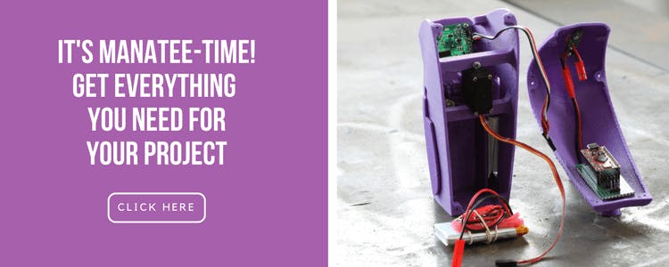
Motion detectors - we meet and use them every day. In our car, at home, in the super market, in our office or when we walk into stores. In this next project, we use a PIR motion detector which can detect movement of people and other living creatures from 20 feet away. The way the PIR sensor work is that it detects levels of infrared radiation. You can read about how this is done exactly in this great tutorial by Adafruit. You can adjust the PIR sensor's sensitivity and also set a delay between readings.
As in all the other projects on this post, we use an Arduino board and in this case an Arduino Pro-micro 5v. As you can see in the image below, we replaced the breadboard with a perforated prototyping board, like we did in the thermometer project. Again, this isn't a must if you're only starting out, but later on these little prototyping boards are a great solution for more permanent project since they are cheap and reliant.
In this project, we also meet the servo motor once more, but this time we only have one motor in the project, as it only moves in one axis.
We wrap up this pretty simple project with a nice casing that keeps the "eye" of the PIR sensor exposed so it can "see" who's coming, but it's elegantly put together in a nice 3D printed case that leaves all the wires and electronics away from the eye, and leaves you with a nice looking manatee that you can put in the entrance to your workshop or garage. It might even keep pests away like a scare crow, how knows? The custom code and 3D designs are on our project hub on Hackster.io.
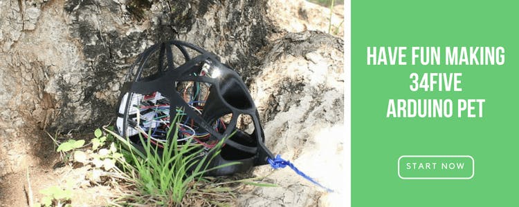
We admit, this is a strange and quirky project, but it got a lot of hilarious reactions. And what’s wrong with having some fun? Plus it's also a good excuse to expose you to another sensor - the accelerometer. As you've probably guessed, it measures acceleration in 3 different axis. You can see the exact calculations and functions of this component on Digikey's Quickstart guide. But the basics of it is that it reacts to changes in orientation. Apart from the accelerometer, we used the piezo speaker again, to play this funky tune according to the changes in orientation. So it's a pet but also a some-what Darth-Vadery portable musical instrument.
As with all of our projects, you can find all the components that we used on our app, and if you click this link, you'll see all the components pre-selected for you, like magic!
More details, code and 3D designs are on our Hackster project hub.
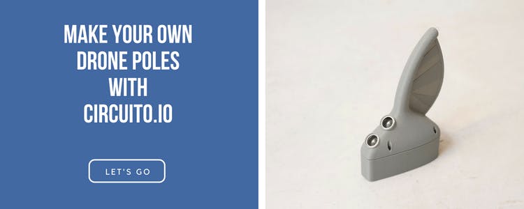
Drones have become extremely popular recently and you can take your playtime with the drone to a new level using this interactive air gate. For this project, what you need includes HC-SRO4 Ultrasonic sensor, 9v battery, Sparkfun Arduino Pro Mini controller and RGB Diffused Common Anode.
The drone poles are great for practicing your flight technique. The ultrasonic sensor detects the drone coming closer and changes the light from red to green. Make as many air gates as you want and build an obstacle course through them to race your friends. It's really fun, believe us. As always, you have the full instructions on our community hub on Hackster.io.
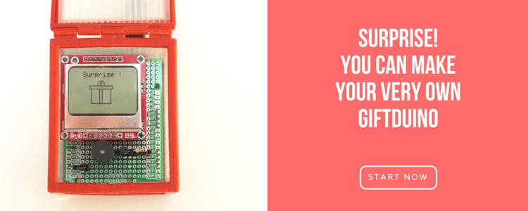
If you’ve reached this far, you deserve a Giftduino!
Having fun is also a big part of the maker-Arduino world, and there’s nothing wrong with making projects that don’t have a purpose.
The interesting component you get to work with here is the A1302 Hall SensorA1302 Hall Sensor. This sensor works on the principles of the Hall effect which means that it reacts to differences in magnetic fields. Therefore, to activate the hall sensor in this project, we placed a magnet on the box's lid. When the box is opened, the piezo speaker starts playing a tune and the screen displays a giftbox (or whatever else you like). In this project you can see that we didn't use a breadboard but rather an Arduino prototype shield. In the meanwhile, you can follow the tutorial and make your very own Giftduino.
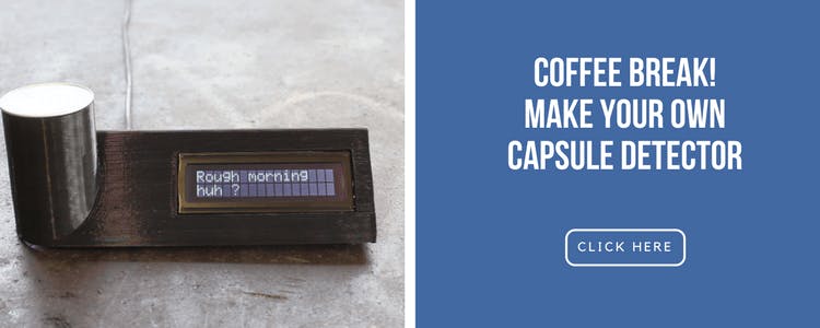
We chose to wrap up our first blog post(!) with our most popular project. The love for coffee is universal and a Nespresso capsule detector can be an amazing gadget to help you choose a capsule.
The mechanism behind the operation of the project is that the RGB light sensor reads the brightness levels of the red, green and blue color channel and sends them to the Arduino, which will recognize your capsule based on the predefined values in the code. The components needed include an RGB light sensor, Arduino pro mini, wall adapter, power supply and serial enabled LCD. Follow the instructions on our tutorial to put together your circuit and download the sample code. Then download the project code from Github, and 3D print the packaging. Assemble them together and voila, you have a coffee capsule color detector.
So now that you have a little bit more information about how this whole Arduino thing work, it's time to get started! Take a moment to prepare your working environment, and making sure that you have everything you need before you sit down to work. The first few projects may be challenging, but it opens up a world of creative possibilities! It's amazing!
We'd love to see the projects you make and hear your comments. Enjoy Making!