10 Basic Circuits You Can Make With Popular Arduino Parts
Hey there, circuit lovers. In this post, we’ll give some simple circuit examples with popular Arduino parts that we add to circuito.io. We’ll be updating new circuits and project ideas to this list from time to time so that you can make cool things with the new Arduino parts we add. In the future, we'll also be adding parts and circuits for other microcontrollers as well. You can use these circuit examples as a starting point, and alter them to your needs. We’ll also throw in some explanations about the parts themselves and the code logic of the circuit, so you can learn something new along the way.
The first Arduino parts we are going to cover are 5 components that have already been on our app for a while, but we recently added code for them:
Before we dive into the circuits, here's a quick reminder about the circuito.io code:
There are two ways to check whether or not the part you want to use has a test code and code libraries on circuito.io.
The code from circuito.io is a test code. This means that it has basic functionality to check that the components are wired up properly. However, most of the test codes also have libraries for the component, which have common functions and commands that can be very useful for your project, especially if you’re a beginner. To learn how to use our test code and other useful information about Arduino code, visit our Arduino code blog post.
Now that we know where the code is and how to use it, we can take a look at the circuit examples!
In this circuit, we are going to learn how to dim an RGB LED strip using a potentiometer. The strip is comprised of 60 LEDs per meter, connected in parallel. Each color channel (R/G/B) is controlled separately, driven by a MOSFET (transistor) controlled by PWM. Setting the PWM value, will drive all the LEDs in the strip.
The potentiometer controls the intensity of the LEDs. Rotating the knob changes the value read by the Arduino. This happens because of the resistance relation between the 3 pins of the potentiometer changes. This causes the voltage in the middle pin to change as well. The readings from the potentiometer determine the intensity of light emitted from the LEDs.
Click here or on the diagram to go to the app >>
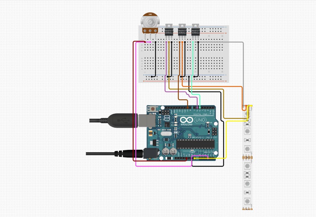
The potentiometer is an analog component, therefore, it’s connected to the Arduino ADC pin. This means that the values read by the Arduino will be in the range between 0-1023. In order to translate the ADC values to PWM values (required by the LEDs) - 0-255, we use the map() function, which is then stored in potentiometerVal variable. Using this variable, we can determine which color we want to control on the LED strip - Red, Green or Blue. The color and intensity of the LEDs will change according to the potentiometer readings and the color we decided to control.
You can find the code for this circuit in our Github repo. Remember to adjust the pin numbers according to the generated code you got from circuito.io.
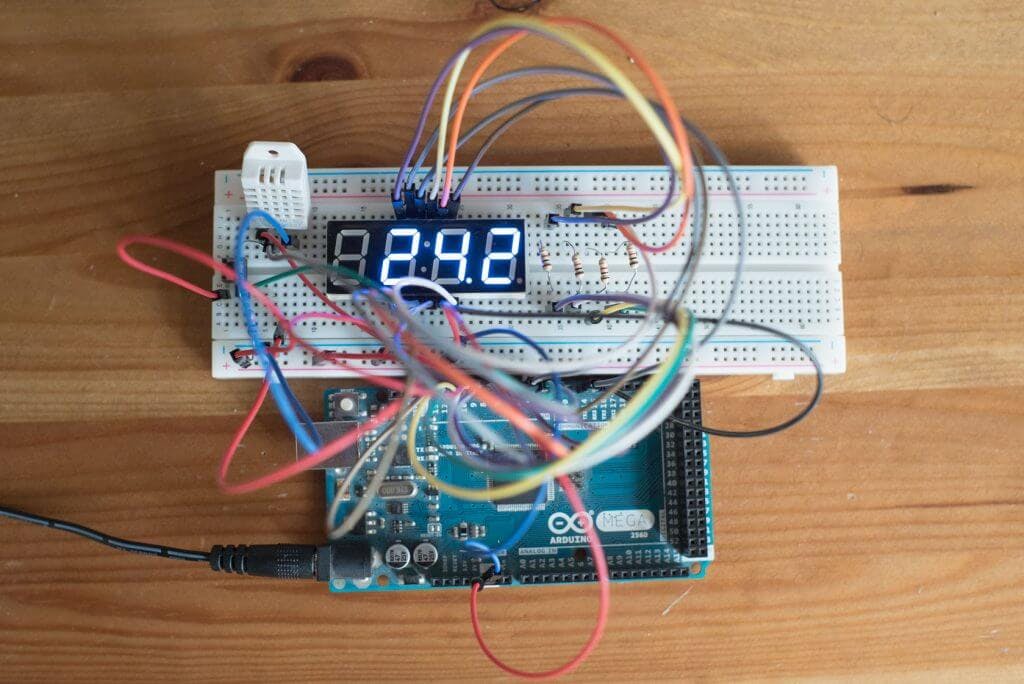
The 3 main components of this circuit are the DHT22 temperature and humidity sensor, push button and a 4 digit 7 segment display. We'll display the temperature and humidity on the 7 segment display and toggle between them, using the push button.
The pushbutton is connected on one side to 5v and on the other side to the GND through a resistor. Using an Arduino digital pin, we are going to determine whether the button is pushed or not. When the button isn’t pushed, the reading is 0. When pushed, the reading is 1.
Click here or the diagram to go to the app >>
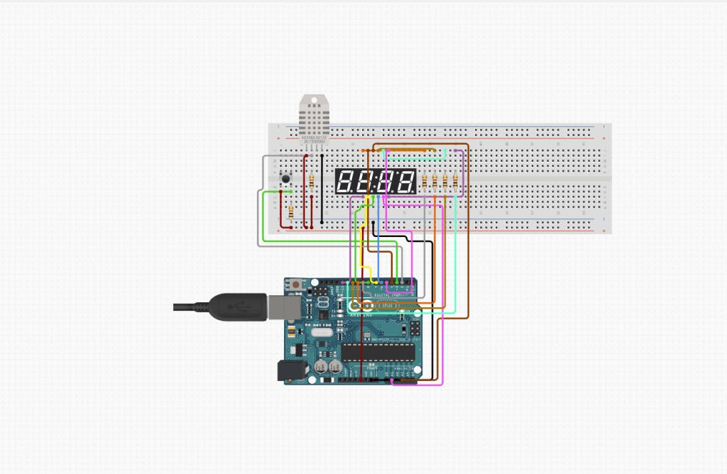
The pushbutton.onPress() function returns the value 1 upon press. When this happens, the display state, which is stored in a boolean variable (since it only has 2 states), will toggle between the states. In the code, this is done using the ‘not’ (!) command. This means that every time the button is pushed, the input to the 7 segment will change.
After the state is defined, it is used to decide which data to display:
You can find the code for this circuit in our Github repo. Remember to adjust the pin numbers according to the generated code you got from circuito.io.
In this circuit we’ll use a microswitch as a limit switch for the stepper motor, in the same way it’s implemented in the calibration setup of 3d printers. We’ll configure the microswitch to change the direction of the stepper motor, every time it’s pressed. You can also set the stepper motor to stop upon press.
The microswitch in this circuit functions in the same way as the pushbutton does in the previous circuit - when the switch isn’t pressed, the reading is 0. When pressed, the reading is 1.
Click here or on the diagram to see it on the app >>
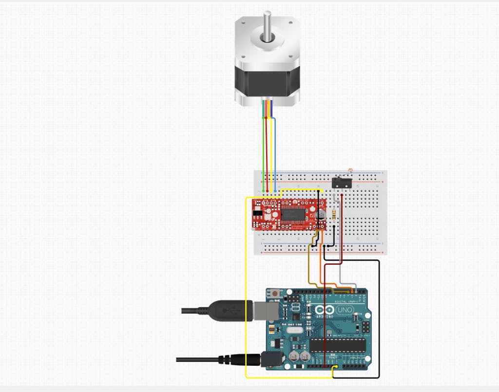
The microswitch.onPress() function returns the value 1 upon press. This simulates the 3D printer calibration and indicates that the axis has reached its limit. When this happens, the motor changes its direction state, which is stored in a boolean variable. This variable is then used in the digitalWrite function on the DIR pin of the ‘Easy Driver’ using digitalWrite(DIR, state).
You can find the code for this circuit in our Github repo. Remember to adjust the pin numbers according to the generated code you got from circuito.io.
For the Arduino clock circuit we’ll use an RTC (Real Time Clock) and an LCD I2C. We’re going to be presenting the time and date on the LCD according to the data received from the RTC. The data will be presented on the screen according to our settings.
We need to set:
As its name implies, the RTC keeps track of the time and date. We are using an RTC module that connects over I2C to retrieve the time and date. The RTC lib does all the communication settings for us. When the RTC doesn’t have power it loses track of time. It is possible to insert a coin battery in order to prevent power loss. Since the RTC has a very low power consumption, the coin battery will last for ages.
Click here or on the diagram to go to the app>>
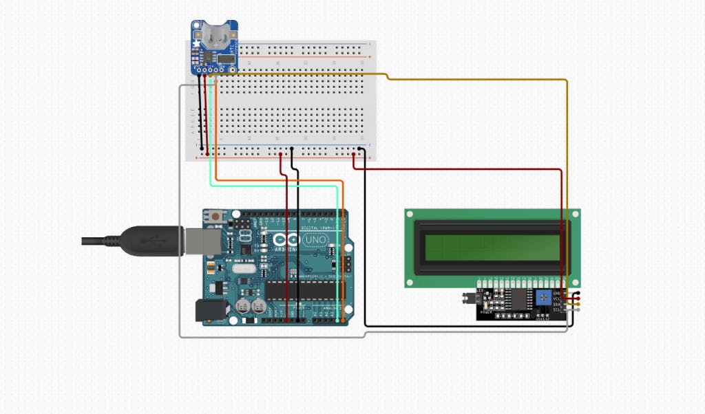
In the setup phase, it is important to adjust the starting time and date on the first startup of the circuit. In the code, this is done by: rtc.adjust(DateTime(F(__DATE__), F(__TIME__))); which gets the current time from the IDE when uploading the sketch.
rtc.now() function will provide us with a data structure holding the current time and date readings. These will be displayed on the LCD using LCD.print() function.
The LCD library provides a few different methods for determining the print location and format on the screen.
The code for this circuit is on our Github repo. Remember to adjust the pin numbers according to the generated code you got from circuito.io.
This circuit will implement a simple code-protected door lock. We used a lock-style solenoid that opens when the correct code is entered.
The keypad is constructed as a 3X4 connection matrix. Pressing one of its keys will cause a short between a row pin and a column pin. This way, the Arduino knows which key was pressed.
Click here or on the diagram to go to the app>>
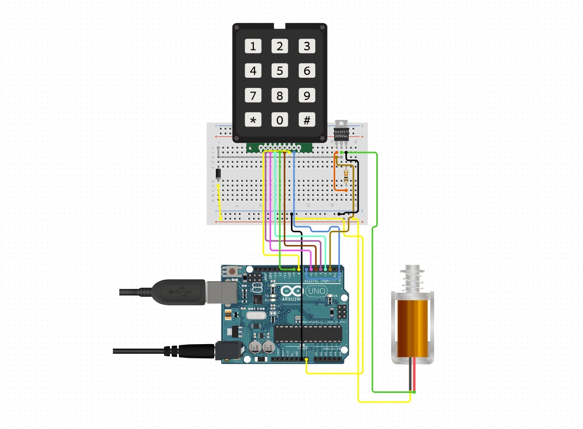
The code maps the keypad buttons into keys, using 2D array. You can set the mapping to whichever characters you want.
In the main loop, the keypad is read continuously, detecting one press at a time. Each press will return a value from the mapping array. This value will be chained into a string, constructing the password. Once the string reaches the correct length, it is compared with the predefined password. If they match, the lock will be released. If it doesn’t, the string is cleared.
The code for this circuit is on our Github repo. Remember to adjust the pin numbers according to the generated code you got from circuito.io.
In this build, we’re going to use a LIDAR optical distance measurement sensor, and display its readings on an OLED.
The LIDAR optical distance sensor by SparkFun measures distance by calculating the time delay between the transmission of a near-infrared laser signal and its reception after reflecting off a target. This translates into distance using the known speed of light.
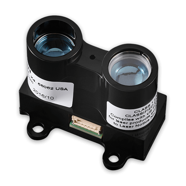
Click the image below to go to the wiring diagram >>
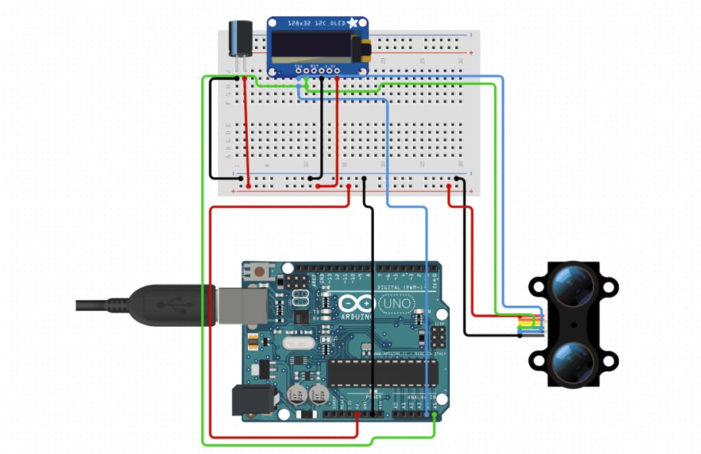
The code for this circuit is very straightforward. We’re going to set a display.print function that will show myLidarLite.distance reading from the LIDAR. The display will be in cm, but you can also set it to inches.
Using two capacitive sensors, we are going to create 4 different combinations to control the relay. You can use this circuit to control different appliances in your home.
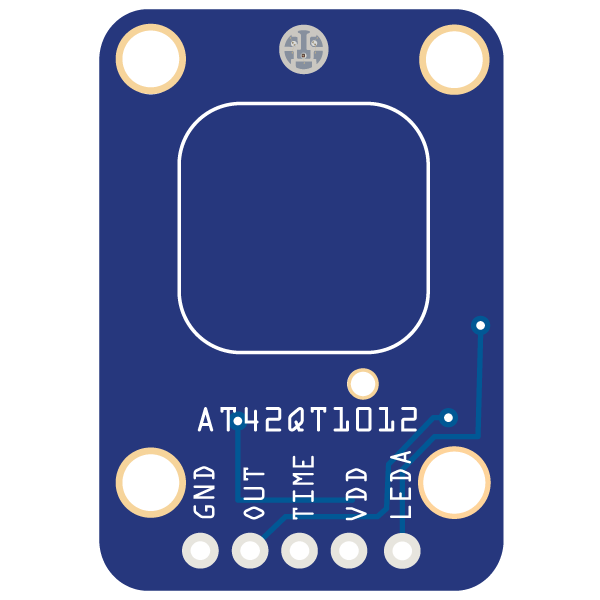
The capacitive touch sensor acts like a switch - touch-on then touch-off. That means that when a person touches the sensor-pad and the capacitive load is detected the output pin will toggle. The on-board red LED indicator will toggle as well.
Click on the image below to go to the wiring diagram >>
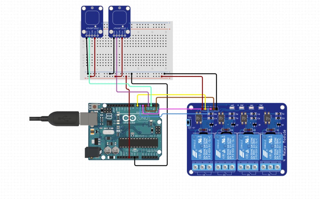
There are 4 conditions in this code, representing the 4 different modes that you can create with the 2 capacitive sensors:
The on-off control of the relays is done inside a for loop. At the top of the firmware code there is an array declaration. It is initialized with the pin numbers of the 4 relay channels. Depending on the value of ‘relayIdx’ calculated above, the relay turns on or off.
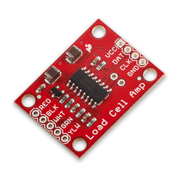
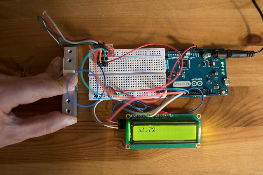
Using a load cell amplifier breakout board and an LCD i2c we’re going to create a simple kitchen scale that will display the weight in the scale units of your choice.
The SparkFun load cell amplifier is a small breakout board for the HX711 that allows you to easily measure weight. By connecting it to the Arduino, we can read the changes in the resistance of the load cell. The HX711 uses a two-wire interface (Clock and Data) for communication.
Click the image below to go to the wiring diagram >>
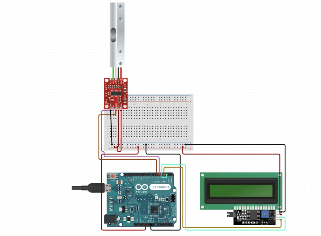
In order to present the data readings from the load cell, we are going to use the scale.get_units() function. We set a float variable - scaleUnits that we are going to print - lcdI2C.print(scaleUnits) on the LCD.
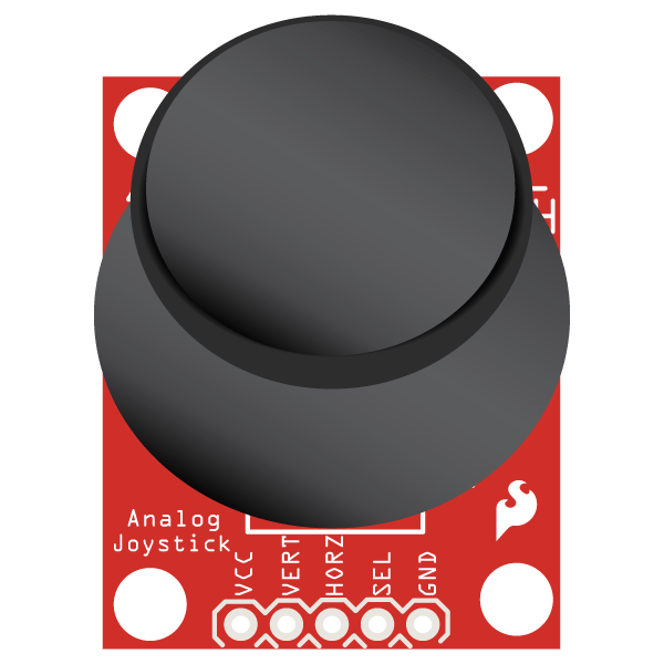
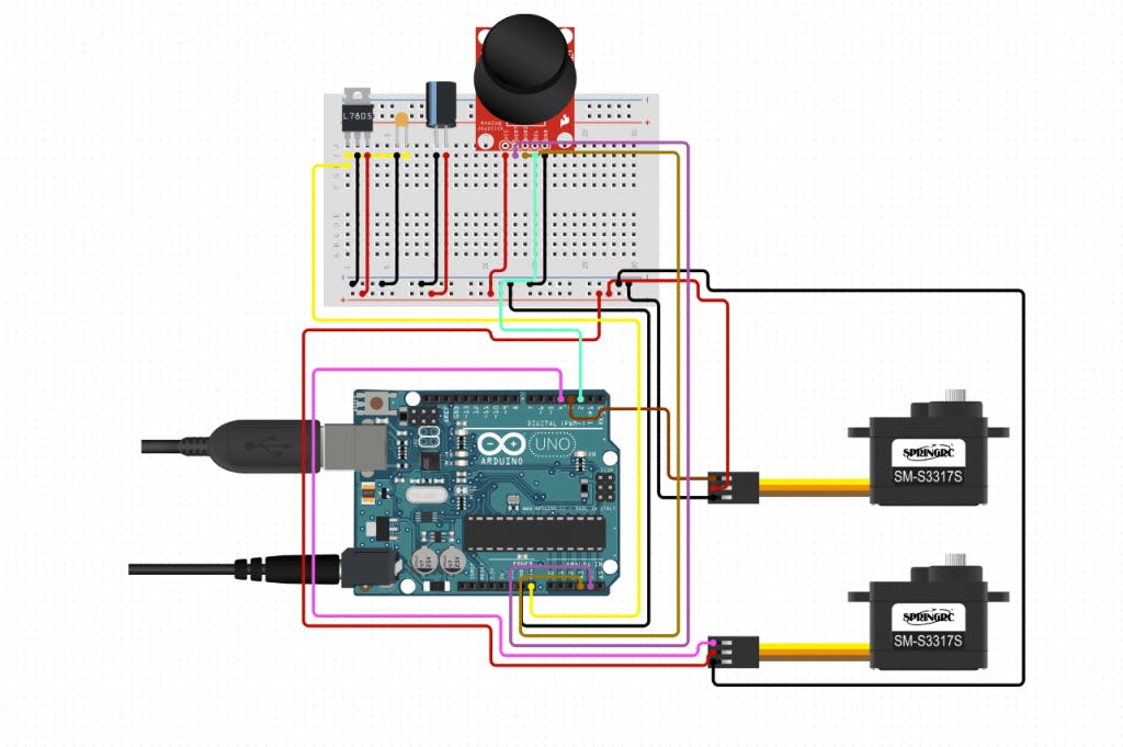
A basic robot consisting of 2 continuous rotation motors, controlled by a joystick. The main logic of the code for this project is the differential between the two servo motors, that allows it to turn in different directions according to the movement of the joystick.
The thumb joystick is very similar to the ‘analog’ joysticks on PS2. Directional movements are simply two potentiometers - one for each axis. Pressing the joystick actuates a select button.
Click the image below to go to the wiring diagram >>

In this project we use the continuous rotation servos as driving motors, like a wheeled robot would.
At the setup stage, we first calibrate the joysticks. We take readings and save their average value for later.
As input for this circuit we use a Joystick, at first we get readings from its two axes. Saving the values in two variables one for the X axis and one for the Y axis.
As always we must map the joystick values into values the servo can understand, this is done after we subtract the calibration values.
After dealing with the data, we need to make our decisions on how to move the motors. In the previous stage, each axis got a different weight, combining them together will turn the motors with respect to the joystick movement in a differential way.
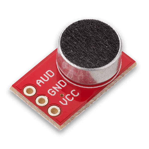
The noise gauge collects sound waves from the environment using the Sparkfun electret microphone and displays its amplitude on the LEDbar. As the signal gets louder, more LEDs light up.
The Sparkfun electret mic breakout has 2 conducting plates, one a vibrating diaphragm and the other fixed. It collects the sound waves between them and converts them into electrical waves. These electrical signals are then amplified and picked up by the microcontroller Analog to Digital converter.
Click the image below to go to the wiring diagram on circuito.io >>
Using the map() function, we are going to represent the readings from the microphone - between 0-500 in the number of bars on the LED bar, between 0-10. Then, in order to accumulate the number of bars, and not just have them light one at a time, we set the for loop:
for (int i = 0; i < numOfBar; i++)
{
digitalWrite(LEDBarPins[i], HIGH);
delay(2);
}
for (int i = numOfBar ; i < 10; i++)
{
digitalWrite(LEDBarPins[i], LOW);
delay(2);
That’s it for now! We’ll update on our facebook page once we add more circuits.
If you have any questions, write to us in the comments below or contact us through our community forum.