DIY Irrigation System
A DIY irrigation system is quite a necessity if you have a backyard or garden. Irrigation systems offer many benefits; Not only do they help with lawn maintenance, they also help you bring down your water bill. It so happens that most property owners end up using way more water than they should, to keep the grass and the landscape looking good. This is not only a burden on their finances, but, also on the available water resources, which, to be honest, are few in number.

Irrigation systems overcome this problem by managing the watering needs of your lawn with more efficiency. Apart from uniform irrigation, these systems provide the exact amount of water your plants need. Therefore, there is almost no wastage at all. And the benefits don’t end there - irrigation systems also save time because you don’t have to manually water your lawn or garden.
Though the long-term benefits are clear, irrigation systems are often expensive and therefore you may want to think about building one yourself! And that’s exactly what we’re going to do today.
In this next tutorial, we’ll show you how you can plan the electronic circuit for a DIY irrigation system with circuito.io.
Ready to start?
Click on the image below to go straight to circuito.io and start your build:
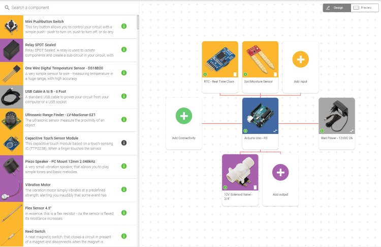
For this build, we’ll be using the following components:
Let’s get a better idea of what each of these components does:
as the name implies, is basically a clock. It tracks the time including current day, month, and year. So in regards to our current project, the DIY irrigation System - the RTC lets the system know when to water your lawn/garden.
In this particular build, we’ll be using the one manufactured by Sparkfun. The moisture sensor has one job to do – measure the moisture levels in the soil. This particular sensor returns values from 0 to 1023; 0 meaning very dry and 1023 meaning very moist. The moisture sensor can trigger the irrigation system once it detects low moisture levels. With the right programming, the system can either water your garden at specific times of the day using the RTC or according to the moisture levels in the soil using the soil moisture sensor. Another option is to combine the two - program the system to water your plants at a certain time but also turn on if the soil gets too dry during the day.

is in charge of regulating the flow of water in the DIY irrigation system. It possesses a push-on terminal connection.
The brain behind the entire circuit is an. The UNO is popular among beginners because it’s easy to use and also, because of how strong and durable it is. The UNO is based on ATmega328P and comes with 14 digital pins each for output and input. 6 of these pins also double as PWM outputs. Other than that, you have 6 analog inputs, a USB connection, a 16 MHz clock, a power jack, and a reset button.
These are the main components of the DIY irrigation system.
In the BoM (Bill of Materials) section you’ll notice that a few components were added to your circuit. These components are necessary for building the specific circuit you are planning, and they are added automatically by our app.
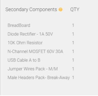
There are two kinds of components in this list:
great for prototyping since it allows you to electrically connect between different components using jumper wires without needing to solder them together and making a permanent connection.
pins that need to be soldered to specific components so you can connect them to the breadboard.
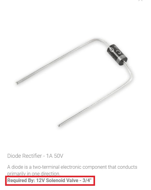
For every component added to your circuit, you can see which part requires it.
A diode is a two-terminal electronic component that conducts primarily in one direction.
Required By: 12V Solenoid Valve - 3/4"
A resistor is a passive two-terminal electrical component that implements electrical resistance as a circuit element.In electronic circuits, resistors are used to reduce current flow, adjust signal levels, to divide voltages, bias active elements, terminate transmission lines and much more.
Required By: 12V Solenoid Valve - 3/4"
The MOSFET is by far the most common transistor in digital circuits, as hundreds of thousands or millions of them may be included in a memory chip or microprocessor. It has an insulated gate, whose voltage determines the conductivity of the device. This ability to change conductivity with the amount of applied voltage can be used for amplifying or switching electronic signals.
Required By: 12V Solenoid Valve - 3/4"
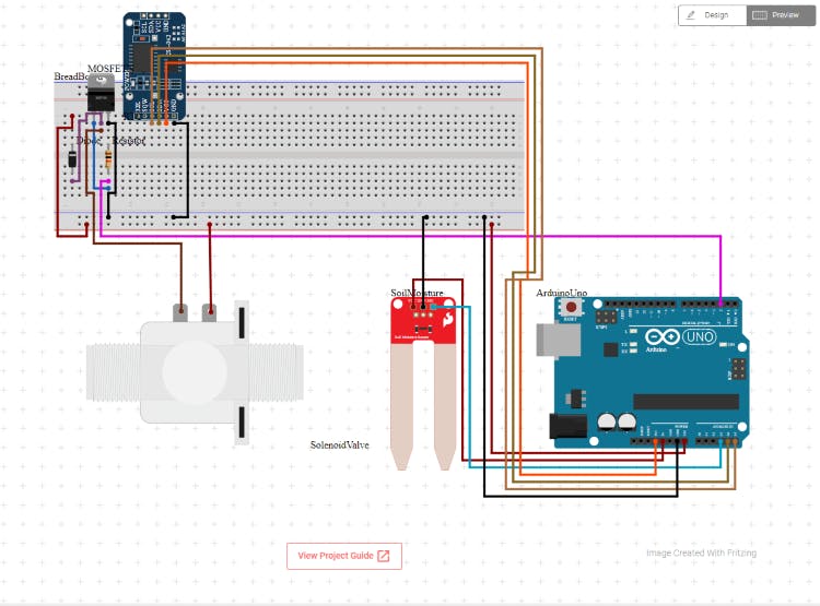
In order to see how to connect the wires step by step, click on the “project guide” tab and click on “wire” on the left sidebar.
After we have the hardware connected, we can start looking at the code.

The code generated automatically is a test code that is designed to help you check that your circuit is set up properly.
You can download this code by clicking on “code” on the left sidebar then clicking download firmware.zip or by clicking on the image below.
Note: It’s important to understand that this is not the final code for your project, this is only a test code to help you verify that your circuit is connected properly. If you build this circuit and program code for it, we invite you to share a link or paste it in the comments
If you have other ideas for projects that you’d like us to help you plan, don’t hesitate to contact us in the comments below as well. Until next time...