DIY Smart Thermostat
Hi everyone, and welcome to another Circuito of the Week. This time we’re going to make a smart thermostat circuit, to help control the humidity and temperature in your home. Like all the other Home Automation circuits, we welcome you to take this example and make it your own by adding or removing components and customizing the circuit to your needs. Circuito.io is here to help you make the magic.
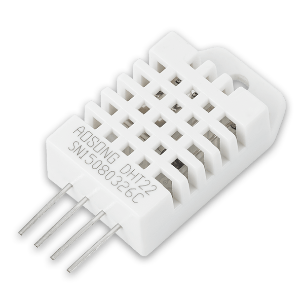
The smart thermostat is based on a temperature and humidity sensor.
Build a Smart Thermostat now >>
We can set the smart thermostat to perform different actions once the temperature or humidity levels rise too high or drop too low. These definitions will be programmed into the controller. Here we chose to use NodeMCU since it has built-in wifi.
The thermostat could have 2 modes, the first automatic, meaning it will self-control the a/c temp and fan speed as well as turn off and on the unit. The second will be manually remote-controlled via the internet. In both cases, the control of the a/c unit will be done by sending an IR signal to the air conditioner using an IR emitter coded with the specific IR code of your a/c. For the second mode, controlling your a/c while you’re not home, you can use an IoT dashboard such as Blynk, or any other IoT platform you choose. You can check out our recommended IoT apps here.
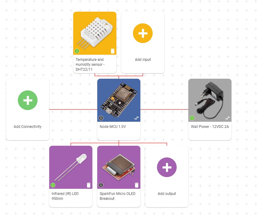
Click this link or the image below to see the circuit components.
‘Secondary components’ is a general name for all the components that you need to add to your circuit in order to make it work. We divide these components into: General secondary components – non-electronic components you can find in almost every circuit. Such as breadboards, jumper wires, etc.Specific secondary components – components added to the circuit according to the specific components we want to use. For example resistors, voltage regulators, capacitors, etc. which are present in order to adjust current flow and voltage levels.You can find information about the secondary components you need for each core component in datasheets and example circuits, and you can also calculate some of their values on your own. When using circuito.io circuit generator, the values of the secondary components are calculated for you automatically.
You can now buy the components for your circuit on circuito.io*! by clicking on Review and Buy on the right bottom corner. It’s also possible to buy the components from any other distributor, online store or local electronics store. We have a list of some great maker-oriented online stores in this link.
Click this link or the image below to see the wiring diagram for the smart thermostat
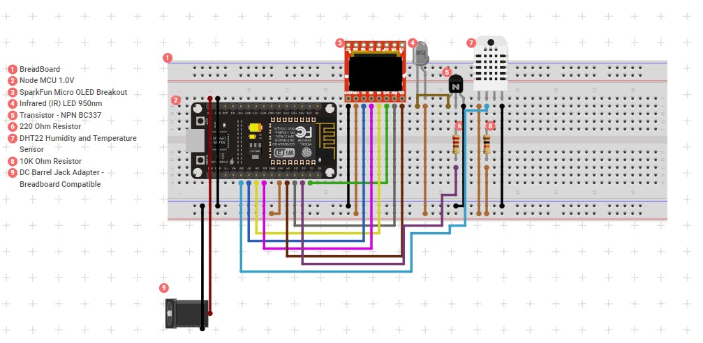
For a detailed step by step wiring guide and test code, click on view project guide at the bottom of the circuit.
After wiring the circuit, you can download the test code from the project guide and upload it to your NodeMCU to check your connectivity. Make sure to choose the correct controller model in the Arduino IDE.
Note: not all the components have a test code. You can check if the component has a test code by hovering over the “i” icon next to the component