Smart Home Security System
Hi everyone! We’re here with another circuit design as part of our home automation circuit ideas. This time we’re going to make a home security system that can save you a lot of money. Traditional home security systems often cost hundreds or thousands of dollars and require maintenance or a monthly fee. Therefore, many homeowners and renters decide not to install these systems. But with today’s IoT solutions, you can build your own home security system, that is customized to your needs and your budget.
Generally, there are two types of electronic home security systems:
The circuit we’re going to show you today is a sensory system. However, that isn’t to say that you can’t also build a surveillance system on top of it, but it may require some heavier coding and possibly more expensive equipment.

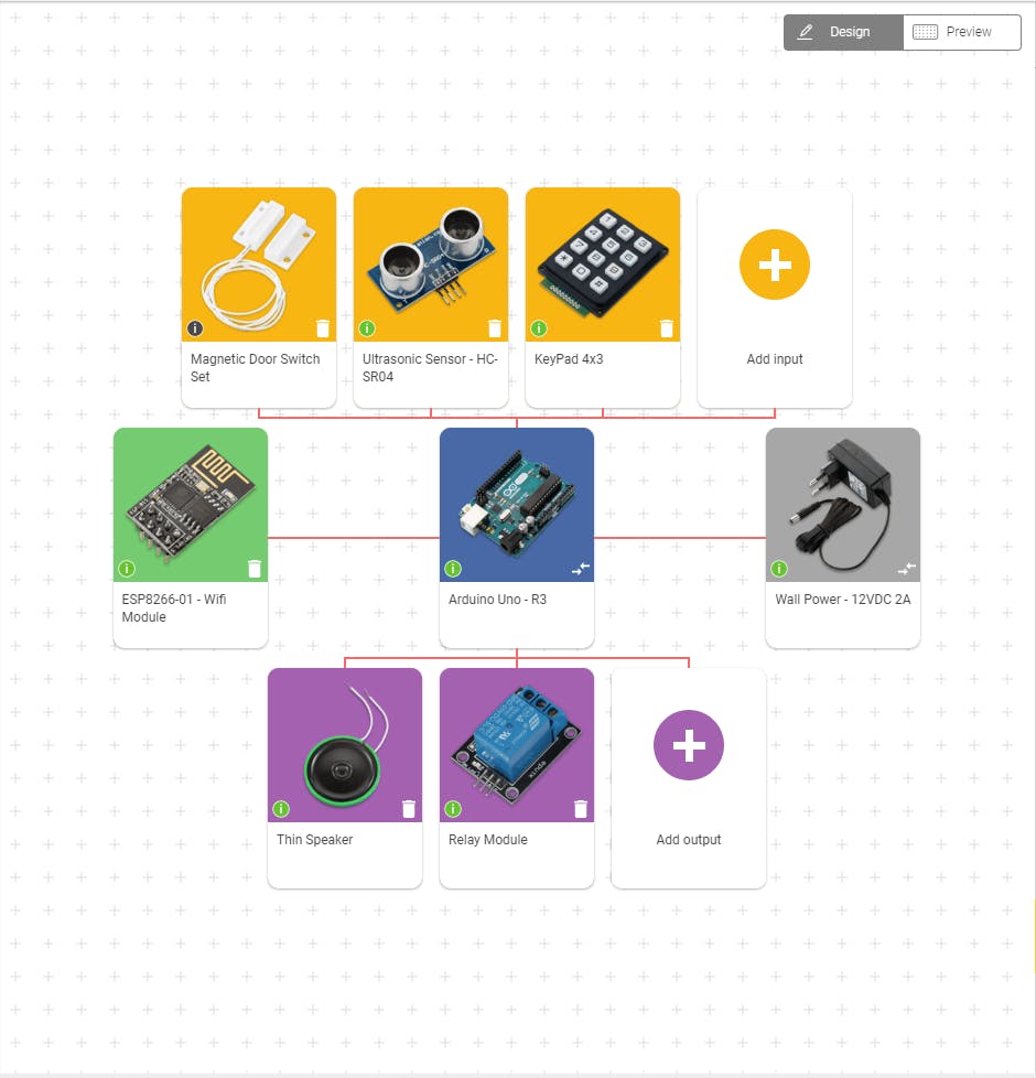
We’re going to put together a circuit that will detect movement using an ultrasonic sensor ultrasonic sensor and detect doors opening using a magnetic door switch. When that happens, a thin speaker and relay switch will be triggered to sound an alarm and turn on the lights, and simultaneously, a notification will be send to your mobile phone through Wifi. The system will be activated and deactivated using a keypad or fingerprint sensor (depending on your choice).
Click this link or the image below to see the circuit components.
‘Secondary components’ is a general name for all the components that you need to add to your circuit in order to make it work. We divide these components into: General secondary components - non-electronic components you can find in almost every circuit. Such as breadboards, jumper wires, etc. Specific secondary components – components added to the circuit according to the specific components we want to use. For example resistors, voltage regulators, capacitors, etc. which are present in order to adjust current flow and voltage levels.
You can find information about the secondary components you need for each core component in datasheets and example circuits, and you can also calculate some of their values on your own. When using circuito.io circuit generator, the values of the secondary components are calculated for you automatically.
Breadboard – best for prototyping. Allows you to electrically connect different components using jumper wires. Jumper Wires M/F and M/M - used for connecting components to the breadboard. USB Cable - connects the microcontroller to the computer, for uploading code.
Male headers - soldered to different components, in this case the keypad.
Logic level converter - used to coordinate voltage levels between 5V controllers and 3.3V components and vice versa. In this circuit it’s required for the ESP8266 Wifi module
10k Ohm resistor - a passive two-terminal electrical component that implements electrical resistance as a circuit element.In electronic circuits, resistors are used to reduce current flow, adjust signal levels, to divide voltages, bias active elements, terminate transmission lines and much more.In this circuit it’s required for the magnetic door switch set.
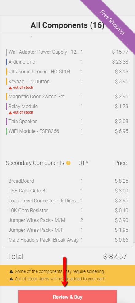
All the components for your circuit can be purchased through the circuito.io website, by clicking on Review and Buy on the right bottom corner.
*some of the components may be temporarily out of stock
You can, of course, buy the components from any other distributor, online store or local electronics store. We have a list of some great maker oriented online stores in this link.
Click this link or the image below for the circuit wiring diagram.
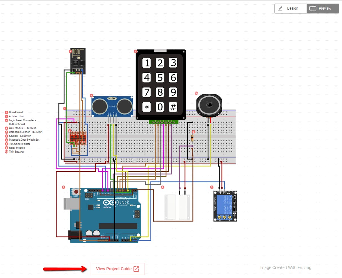
After you’ve put together the circuit, you can download the test code from the project guideproject guide and upload it to your Arduino to check your connectivity.
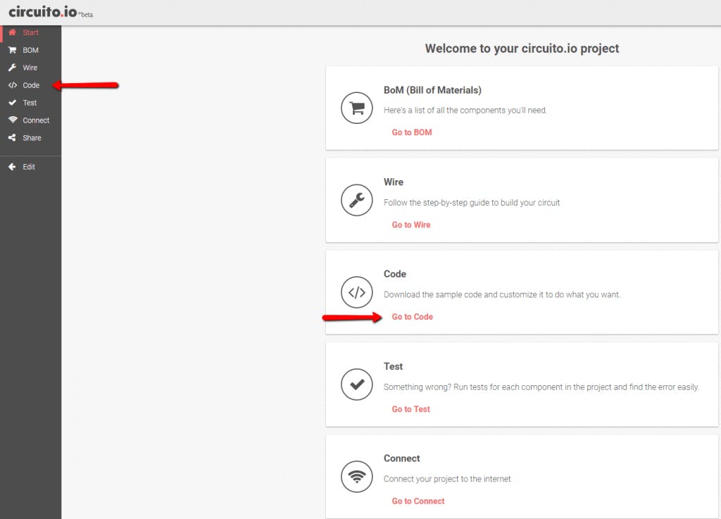
You can also access the code by clicking the image below and clicking on code.
That’s all for this time. Now that you have the circuit set-up, you can start programming it to your needs, adding or removing components according to your personal preferences.
We hope you found this guide helpful. Let us know if you have any comments or questions.