Circuit Design Tools for Your Electronics Project
Circuit design is everywhere. From your phone to your oven to your TV remote, there’s no escaping it. But that’s not a bad thing; without circuits, we’d be unable to harness the power of electricity to do useful things. Cars would be less reliable and safe to drive; displays would be less sharp and more power-hungry. Computers and the internet wouldn’t exist. The fact that electrical components are constantly getting smaller allows complex circuits to be installed into smaller and smaller spaces, and thus just about everything we own might soon include some form of integrated circuit design.
Creating great circuits requires great circuit design and great circuit designers. These talented people connect electrical components to one another to produce useful results, gradually refining the circuit until it’s ready for production. It’s a skill that’s built through practice and study, and that can be improved with the help of the right tools. Just as a mechanic can easily change a tire with the help of the right jack, electrical engineers can assemble a prototype with the help of a suitable circuit design tool.

As you might have guessed, we provide exactly such an electronic circuit design tool. It generates accurate schematics instantly, along with the code required to bring those schematics to life. Specify the major building blocks via the graphic interface, and you’ll get the code, parts list, and step-by-step instructions. It streamlines the design process, breaking down complex projects into achievable chunks and allowing even relative newcomers to the world of electronics to achieve quality production designs.
Let’s run through some of the specific problems you might encounter while developing your project, and explore how circuito.io can tackle them.
To put together a circuit that does the job, you’ll need to select the right components. Doing this manually, even with the help of a well-designed online store, is awkward and time-consuming. The browser-based design software eliminates this. From the design tab, you’ll pick out the components you need and, with the help of an intuitive GUI, assemble them into a functional electronic circuit.
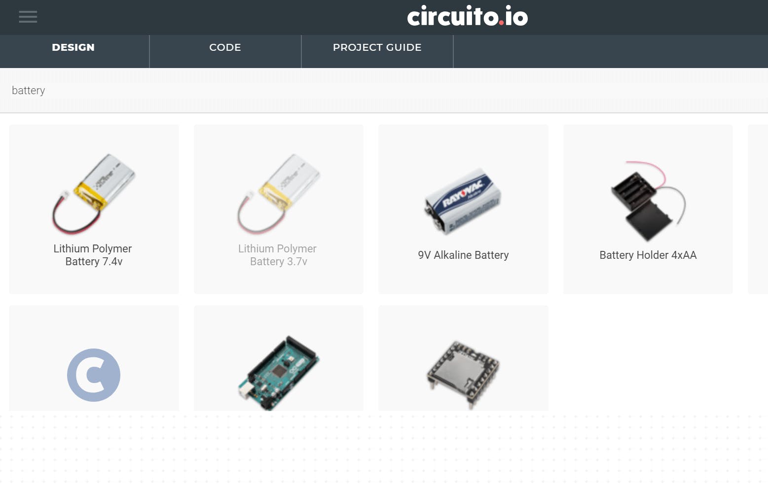
When you first open the design tab, you’ll be confronted by a list of usable components. You can manually hunt through them in search of the one you’re after. But there are hundreds of components to choose from, ranging from mechanical pumps to LEDs, so rather than manually looking through it, you can use the search bar. This will allow you not only to find your component quickly but to see the range of options available within the same category. That way, you’ll be able to track down precisely the component you need in moments.
So, for example, you might need a battery to power your project. In which case you’d simply type in – ‘battery’, and select from the list of available batteries:
While we try to provide as broad a selection as possible, you might sometimes need a component that we haven’t introduced. If that happens, you can request a specific component using the button at the bottom of the components list.
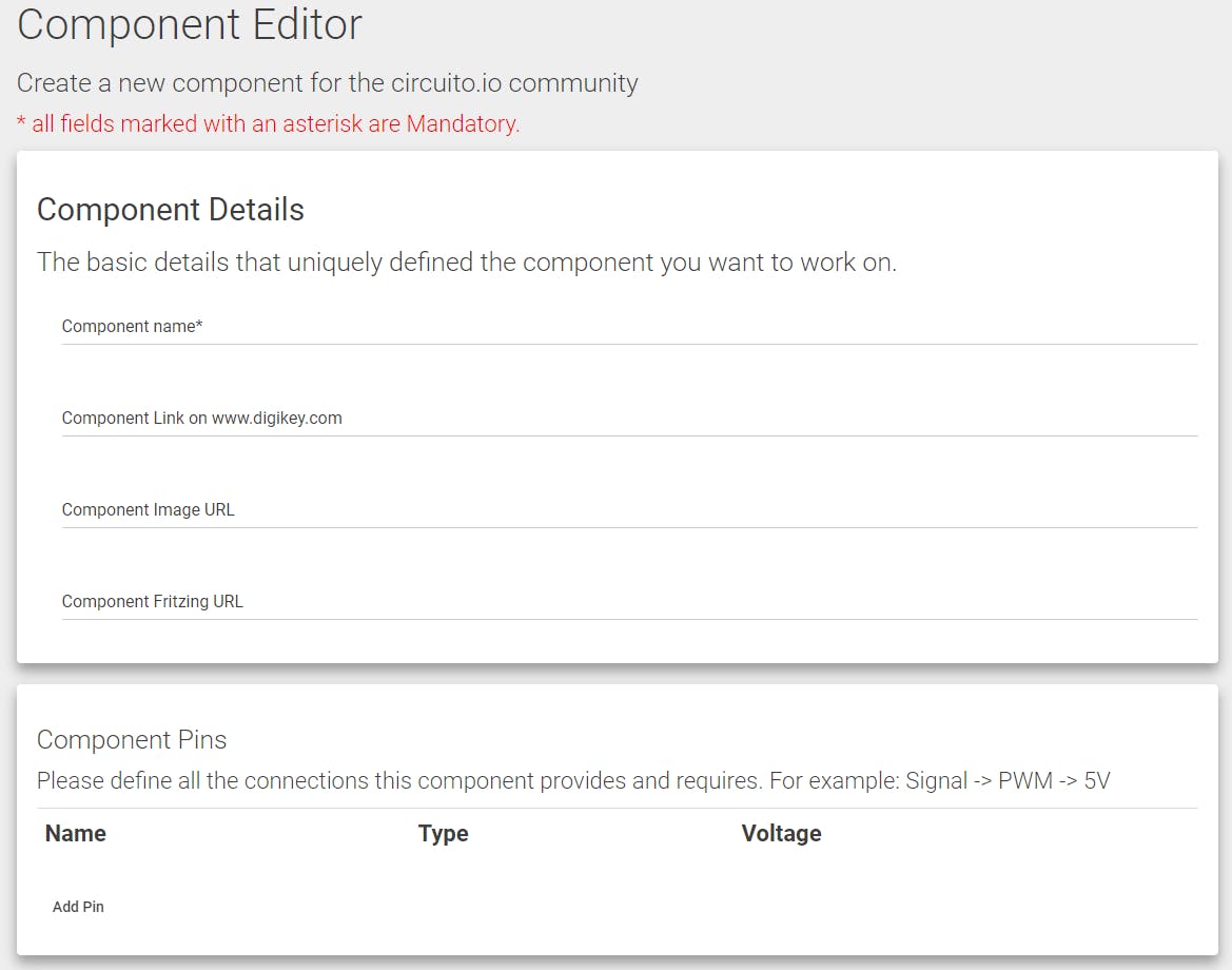
This will take you to the development section, where prospective new components are defined before being added to the list. By submitting as much information as possible about the new part you’d like us to add, we’ll do our best to incorporate it as quickly as possible. In this way, our users help us to gradually build up our circuit design tool’s database!
The design part of the tool works via a drag-and-drop interface. Drag the parts you want to incorporate into your project from the selection on the left into the circuit on the right. The circuit design tool will automatically throw in any required secondary components, which normally take the form of breadboard(s), capacitors, resistors and so on. As such, you’ll be able to focus on choosing the components that actually change what your circuit does, rather than having to wrestle with the little ones. You can always tweak these later in your physical circuit when you’re fine-tuning the way it performs before creating a final PCB layout.

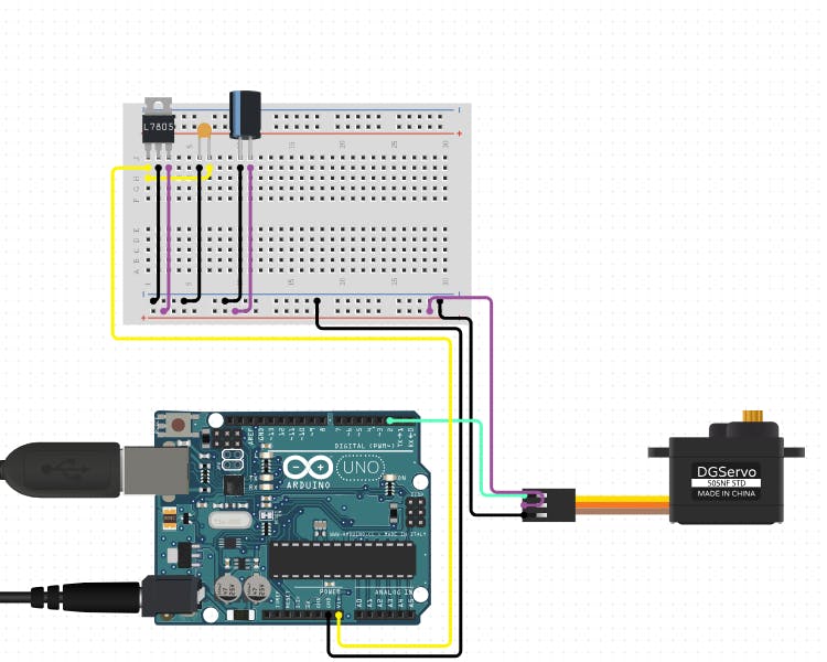
For example, if you’d like to use an Arduino UNO to drive a servo, just drag the two components into the empty space. The app will automatically generate a breadboard, along with a 5v regulator, a small ceramic capacitor and a larger electrolytic one. The three components will work together to ensure that your servo receives consistent voltage. This will help it to function properly, and last as long as possible. In this way, your production design can be made robust and reliable without overcomplicating the design process.
Most helpfully, the graphic display will also illustrate where to connect each wire – allowing you to see at a glance how your finished breadboard will look, and to move onto a printed circuit board more quickly.
To see the values of each secondary component at a glance, simply hover over it with your mouse. These values are calculated automatically according to the needs of the circuit so you won’t need to spend any time remembering how to calculate resistances and amperage.
Once you have assembled your circuit board, our design software allows you to make changes by left-clicking on a component you'd like to change. Depending on the component in question, you’ll be presented with up to three options in a menu. These are fairly self-explanatory:
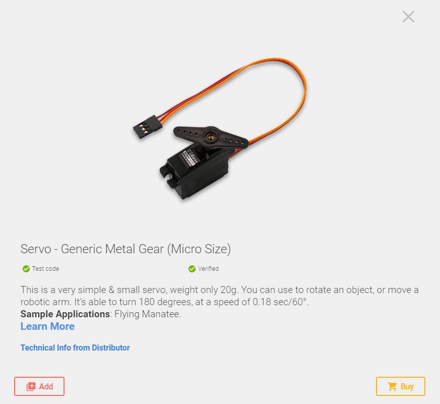
View Info
Brings up a description of the component. This includes an image, along with information about its dimensions and applications. There is also a link to the distributor’s site, where you can get more info. You’ll also be able to see whether the component has been verified and whether it’s in stock.
Duplicate
Creates another, identical component, along with all the necessary wiring.
Remove
Removes the component from your project, along with the associated components and wires.
Note that it isn’t possible to alter the values of capacitors, resistors and other supplementary components. As such, you don’t need to worry about accidentally swapping something in that’ll fry your other components, or produce unwanted results in your final production design.
At the heart of your circuit design is a microcontroller board, containing a microcontroller and a range of other useful integrated circuits and supporting components. This central component can be swapped out for another by left-clicking on it and selecting ‘swap’. You’ll then be presented with a list of similar devices. By swapping out an item in this way, you’ll be able to preserve all the connections and wiring, and potentially save yourself the trouble of figuring out which cable connects to which GPIO port. That way, your choice of microcontroller will reflect the needs of your project, rather than your desire to avoid having to figure out a new wiring solution for each prospective candidate.
The various available microcontroller boards differ in terms of their connectivity and power requirements. But the tool will allow you to easily compensate for this. Swap an Arduino UNO with an Arduino Gemma v2, for example, and you’ll find that the circuit design tool automatically inserts an additional component: a breadboard-compatible DC-barrel jack adaptor. This is because the board itself is too small to accommodate one.
Of course, it’s not enough to simply strap your components to a microcontroller and wait for the magic to happen. For your circuit to function, you’ll need to provide the microcontroller with the necessary code. This presents several problems. Firstly, coding is laborious. You might already have an idea of what the code should look like, but doing the actual programming it could take hours of your time. And what if you don’t know where to start – not everyone is fluent in C++, and those that are only become so after years of practice.
Happily, our circuit design tool cuts out much of this problem by providing test code. You’ll be able to import it into the Arduino IDE and from there to your circuit and achieve a functioning electronic circuit as quickly as possible. From there, you’ll be able to refine the code until you've arrived at a production design that suits your precise purposes.
If you’re dealing with an especially long and complex stream of code, then remembering exactly what does what can be very tricky. That’s why leaving explanatory comments, each prefaced with a ‘//’, is such a good habit to get into. It makes collaborating with other members of a team, and future versions of yourself, much less stressful.
Our circuit-design tool makes notes of this sort automatically: each block of code is generated with a note attached. This is useful for new coders who aren’t fluent in the commands just yet. Comments are also sure to make life easier for more experienced programmers, who’ll be able to understand of what each line does at a glance.
Often, blocks of circuit code (called ‘sketches’ in Arduino), refer to code kept in separate ‘library’ files. You can easily identify such projects in the Arduino IDE, as they insert an #include statement at the top of the sketch. Having done this, the sketch can refer to functions and statements that are defined in the library rather than in the sketch itself. This makes life easier in several ways. Firstly, it eliminates clutter in your project, which in turn facilitates troubleshooting. Secondly, libraries can hold frequently-used functions that are shared by multiple projects.
We’ve worked hard on the libraries we provide to ensure that they’re highly optimized and adaptable to just about any project. The app will calculate the amount of memory required by each library to ensure that it fits onto your device. In some cases, you might be able to get away with a smaller, more affordable microcontroller board; in others, it might make sense to switch to something more spacious. Whatever the needs of your project, our circuit design tool makes swapping out the controller easy.
‘Include’ statements signal to the compiler that the sketch and the code are to be incorporated – so in practice, the two are treated as a single entity. For coding purposes, it’s helpful to keep a few commonly-used functions in a separate library file, to which the main code can refer. The circuit design tool will incorporate these automatically, making the design process as painless as possible.
Note that the code generated here is just a preview, so don’t simply copy+paste it into your development environment; instead, download the associated firmware.zip file, which will contain everything you need to make your circuit design come to life, including the firmware.ino file and any libraries specific to the components you’ve put in place. Open the firmware file in your Arduino IDE and compile it. If you have everything wired up correctly, you should then have a functioning electronic circuit!

Currently, our circuit design tool is focused on Arduino. However, we are in the process of introducing new microcontrollers to the library, including Raspberry Pi. You’ll see the words ‘alpha’ or ‘beta’ next to these newer MCUs. The environment will wire them up for you, but it won’t generate code – yet.

The ‘Parts’ tab will list your components into two categories – the primary ones, which make your circuit board run, and the secondary ones, which make your primary components run. You’ll be given an indication of whether your chosen component is equipped with test code and whether it’s been verified by our team.
Getting the parts together is one thing. But you’ll also need to wire them up to one another for the design to become a functioning, real-world circuit. And the more connections a project requires, the more difficult making them will be. This is something that our tool can help with.
Unfortunately, no circuit-design tool can wire up your breadboard for you. But ours can do the next best thing: provide you with easy to follow, step by step instructions. That way you’ll minimize time spent frowning at a spaghetti of wires, trying to remember which does what. What’s more, you won’t need as much technical experience to get your circuit running.
Once you have everything wired up and your code compiled, you might expect everything to work perfectly. If you’ve followed the provided instructions, then this might well happen. However, if you’ve been building circuits for long enough, then you probably know that things don’t always work out that way. Methodical troubleshooting is, therefore, a crucial skill if your circuit is going to succeed. And the more complicated your final printed circuit, the greater the potential for failure, and the more important hardware debugging becomes.
Electronic circuits can go wrong in all sorts of ways. Perhaps you’ve threaded a wire into the wrong hole in your breadboard or inserted a diode the wrong way round. It might even be that one of your components is faulty. Picking out and testing each component one-by-one is not much fun.
The test code we provide can speed up this process. You’ll find the ‘test’ section in the project guide.
The testing is done using the IDE serial functionality. You’ll be instructed to actuate the sensors and observe the outputs, one-by-one. Does a humidity sensor pick up data when you breathe on it? Does an LED light up? This method eliminates the need for annoying wiring and rewiring and allows you to pinpoint the problem.
We went through the basic functions of our circuit design tool. We tried to make it as intuitive and user-friendly as possible so that you can figure out what you’re doing as you go along. If you get stuck, however, be sure to check out our FAQ – or our forum.
We are constantly expanding our circuit design software by adding new functions and components. With their help, you’ll be able to cut out a lot of menial work and focus on the creative thinking that’ll actually improve your printed circuit. We hope that it’s already part of your circuit design tool-kit, and we’d love to hear your suggestions and ideas for new features and improvements!
