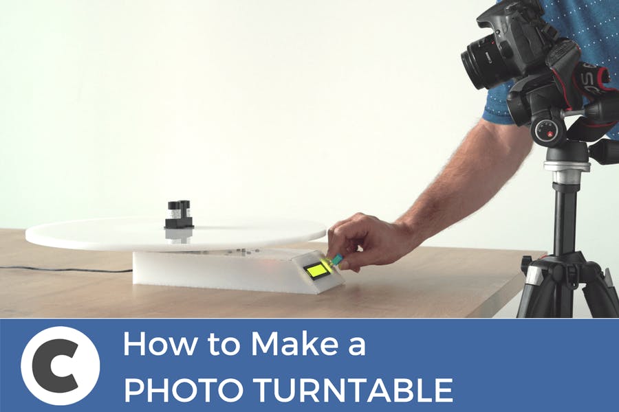
What’s a photography turntablePhotography turntables are round docks used by photographers to take images or videos of objects or people in 360°. The idea is that the object itself sits in the exact middle of the plate, while it spins, either manually or automatically, so you can get a good shot of the product from every angle.
![]() Why did we decide to build one
Why did we decide to build oneSometimes we need to take images of the components we add to circuito.io, and a photography turntable is useful for taking pack-shots from different angles. Also, we like to take good photos of the circuits and projects we build. Plus, it’s a cool project!
What’s special about our photography turntable
It's Automatic - the photography turntable is fully automatic, meaning that you don’t have to spin the table or click your camera
Camera-table Sync - programmed to trigger both table and turntable (only for Cannon at the moment, sorry Nikon). Once you push the button, it both turns and triggers the camera, so you can sit and relax
Accurate and easy to setup - we used a stepper motor which gives you much higher accuracy and control over the angle you want to shoot
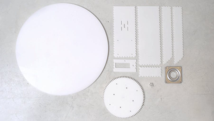
MechanicsLaser cut partsThe photography turntable has 4 Laser cut parts. We used white Plexiglass in 3 different thicknesses, depending on the part. Pololu offer an affordable laser-cutting service.
The parts are:
Round plate - 10mm Plexiglass2 Gears - 8 mm plexiglassBase casing - 3 mm plexiglassYou can find the .ai files on Thingiverse.
![]()
We designed the gears using geargenerator.com, then exported them to Illustrator and added drilling holes for screwing the pieces together.
In the small gear, we made the drill holes slightly smaller so it sits tightly on the stepper motor.
We used makercase to design the case and chose t-slots which we glued together. After designing the case, we exported the file to Illustrator, and made room for the LCD display.
Materials and toolsTo connect the plate, gears, and casing to one another you’ll need:
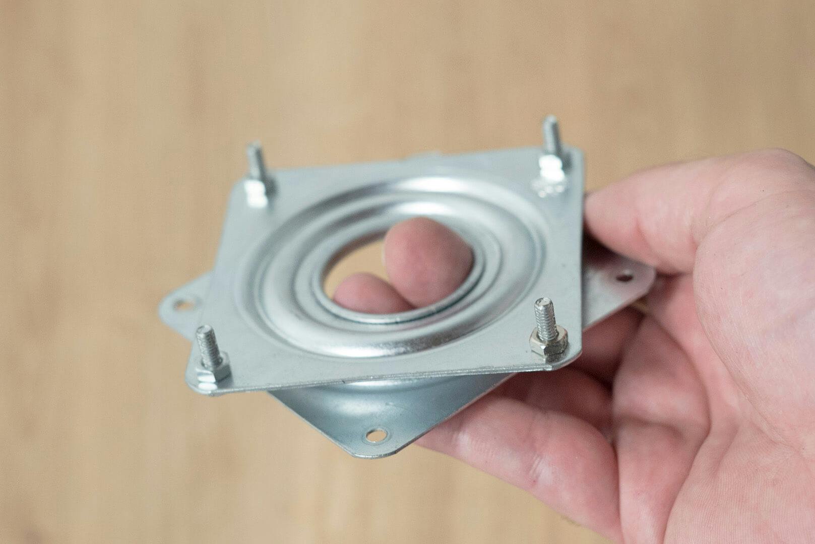
Lazy Susan bearing4 X M3 12mm screws4 X M3 16mm screws8 X M4 12mm screws8 X M4 nuts4 x M3 Brass threaded inserts8 x M3 5mm Female Threaded Brass Hex Spacer OR 8 x M3 5mm Brass threaded insertsMaterials:
Acrylic glueSuper GlueTools:
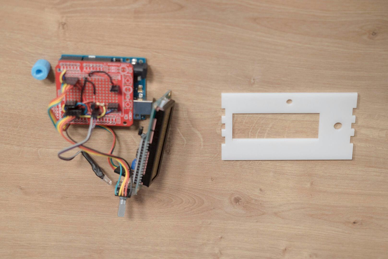
Electric drillSoldering ironCaliper ElectronicsClick the image to see the components you’ll need for the build:
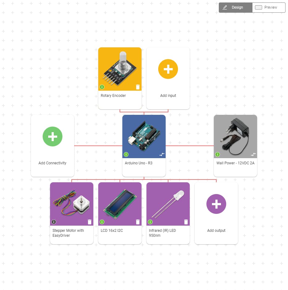
![]() Main componentsArduino UnoStepper motorRotary encoderLCD 16*2 I2CIR ledSecondary componentseasy driverTransistor + ResistorFemale Barrel jack Wiring
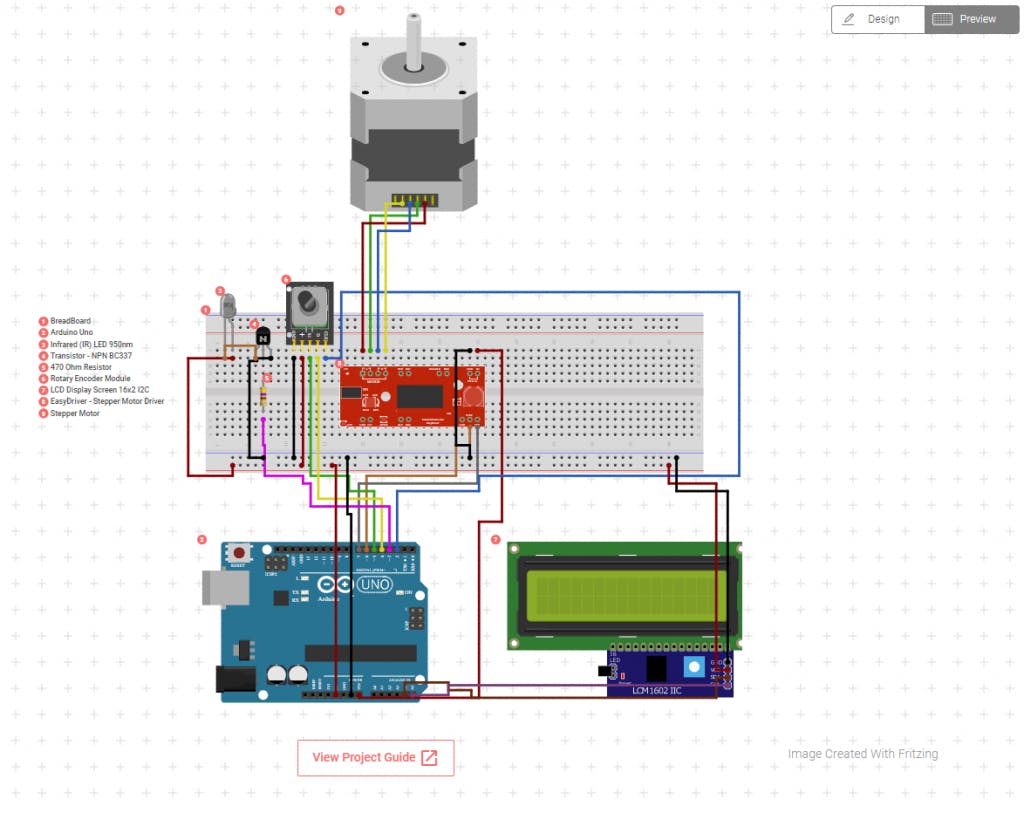
Main componentsArduino UnoStepper motorRotary encoderLCD 16*2 I2CIR ledSecondary componentseasy driverTransistor + ResistorFemale Barrel jack WiringClick the image below, then click on “view project guide”. Then, follow the steps on the app to connect the circuit using a breadboard.
![]()
Once you verify everything is connected properly and working, you can make a small shield. Shields are better for permanent circuits and they are more compact. Breadboards, on the other hand, are good for testing and planning because you can connect and disconnect components easily.
Why we chose these componentsStepper motor - accurate and easy to use. Programming the stepper motor is much more simple because you can set it to count the number of steps between the angles.Infrared LED for camera trigger- we wanted a wireless connection with minimum setup. We found the IR code for a Canon camera and set it up accordingly. You can do the same for Nikon.Rotary encoder - we decided to go with a local option for the menu and add an LCD screen with a rotary encoder. You can also hookup a Wifi module and create an IoT dashboard to control the photography turntable wirelessly. CodeSteps to use codeUpload test code from circuito.io to check the circuitVisit Github repositoryDownload photo-turntable.ino Copy code from line 16 (leaving “include libraries” and “pin definitions” from the original code)Make sure that the pins are set correctlyUpload new codeCode LogicThe code implements a basic menu using a 16x2 LCD and a rotary encoder which also has a pushbutton.
Throughout the Firmware.ino you can see:
pin declarationscomponents settingsconstructors setup() function provided by circuito.io.The loop function starts with reading the rotary encoders state, Left or Right, and its button as well.
The menu is implemented using a switch-case finite state machine - navigating through the different states:
HOME - idle VIDEO - enter video modeSTILLS - enter stills modeToggle between states using the rotation of the encoder.
Select by clicking the button.
The two states: SPEED and ANGLES allow you to modify the variables responsible for the number of stop points in stills mode and the speed of rotation in video mode.
VIDSTART - calls the video() function:
Sends the start recording IR code to the camera using the IR LED.Starts the table rotation at the chosen speed for a whole rotation.Sends stop recording IR code to camera using IR LEDNote:
For a smooth start and stop of the table, we implemented cubic acceleration and deceleration on the first and last 600 steps.
STILSTART - calls the stills() function.
divides one full rotation by the number of set anglesFor each angle it sends the single stills shot IR code to the camera using the IR LEDStarts the table rotation until reaching the next angleNote - For a smooth start and stop of the table, we have implemented cubic acceleration and deceleration on the first and last 600 steps.
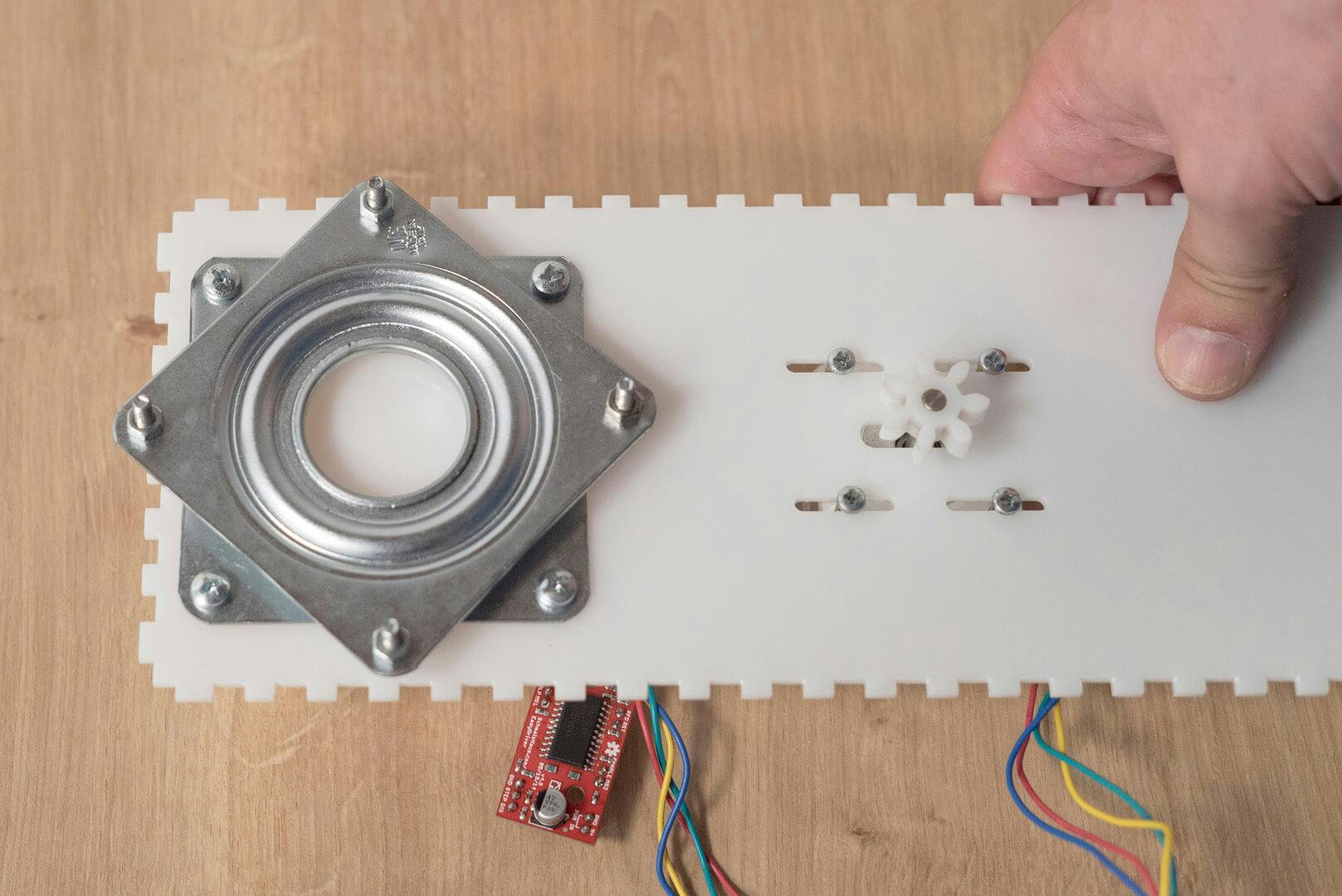
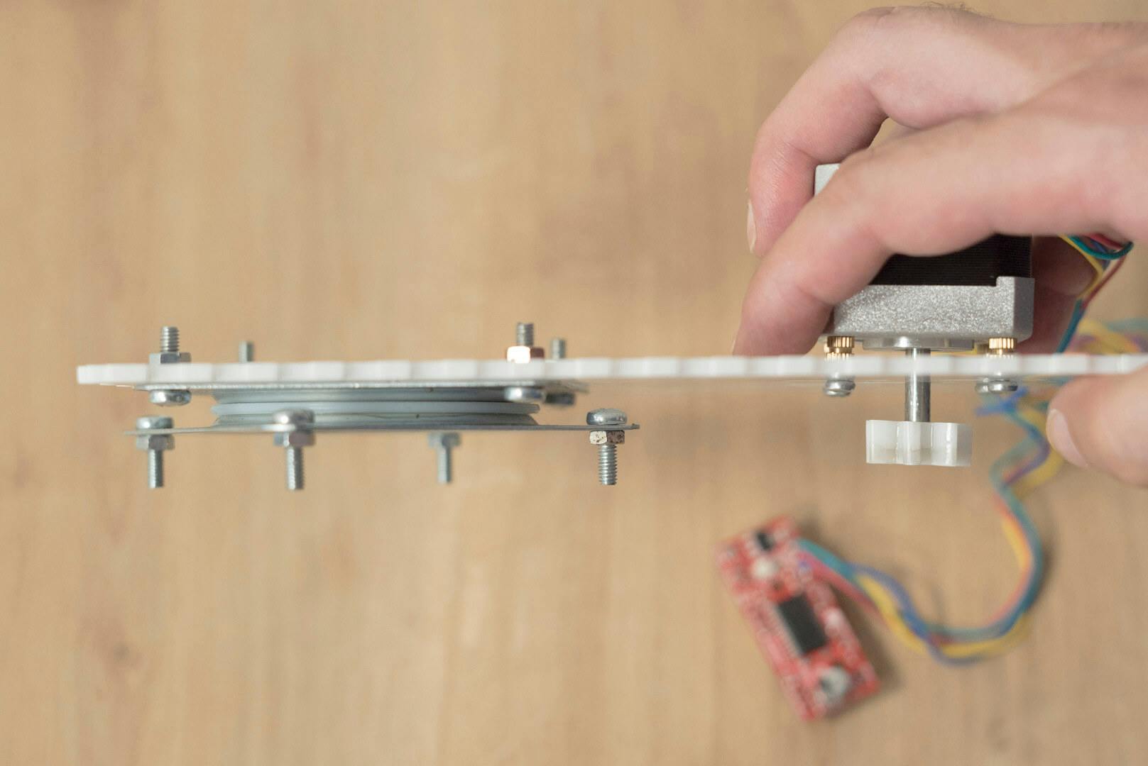
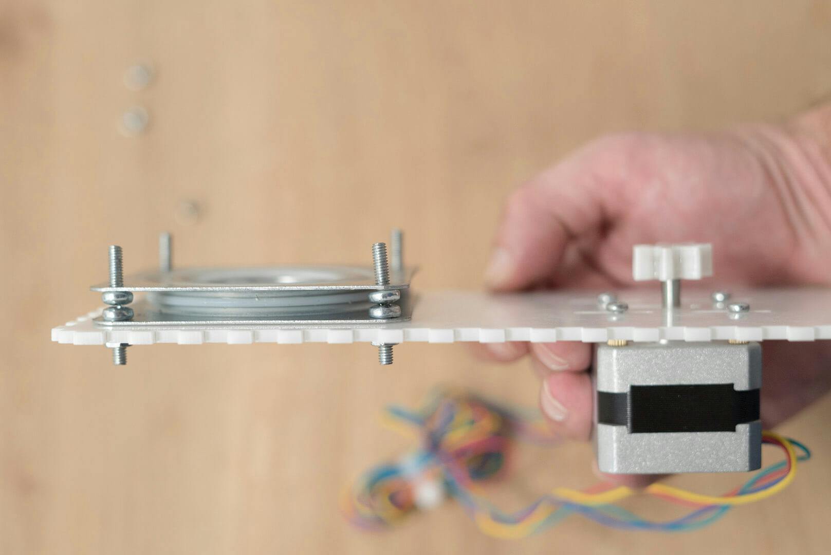
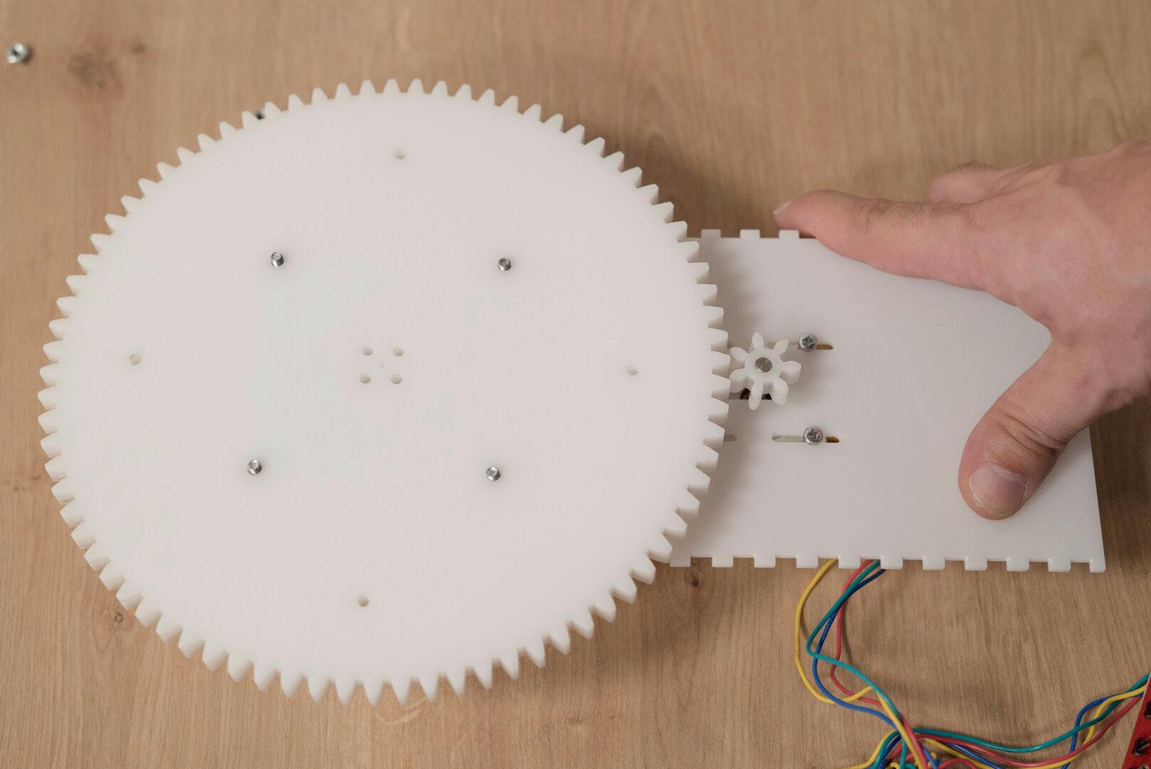
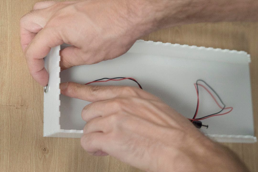
Putting it togetherFollow the instructions together with the images (from left to right):
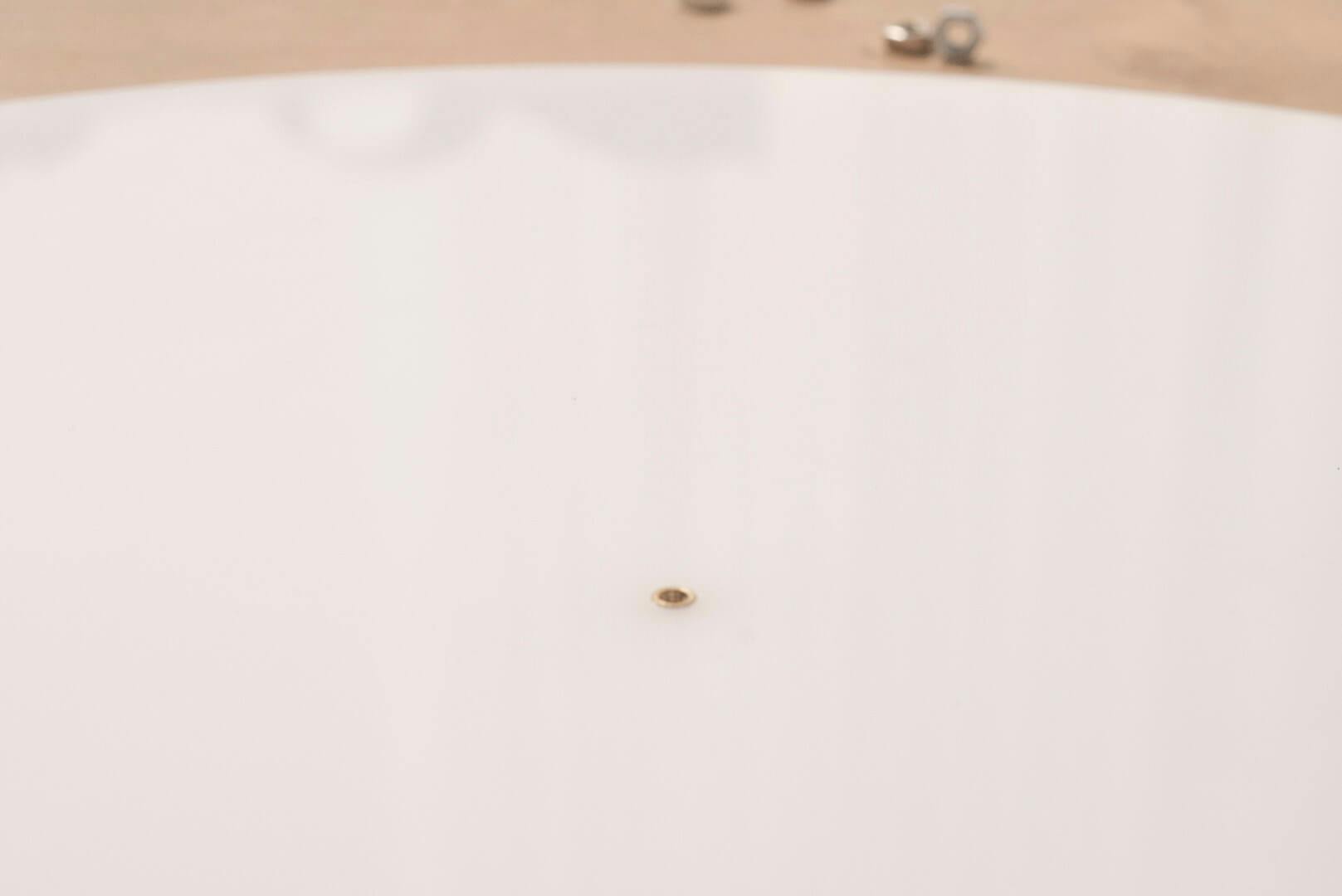
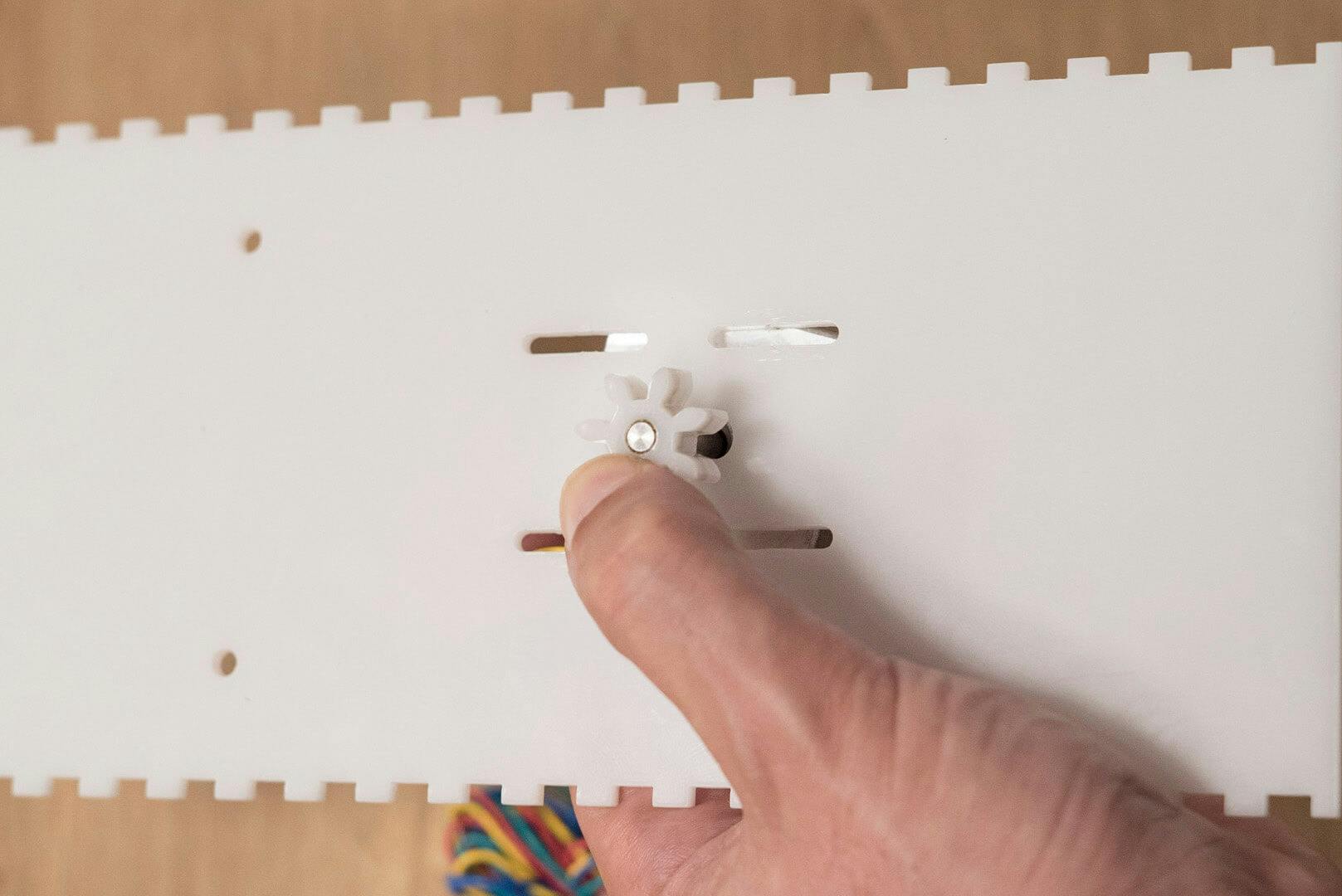
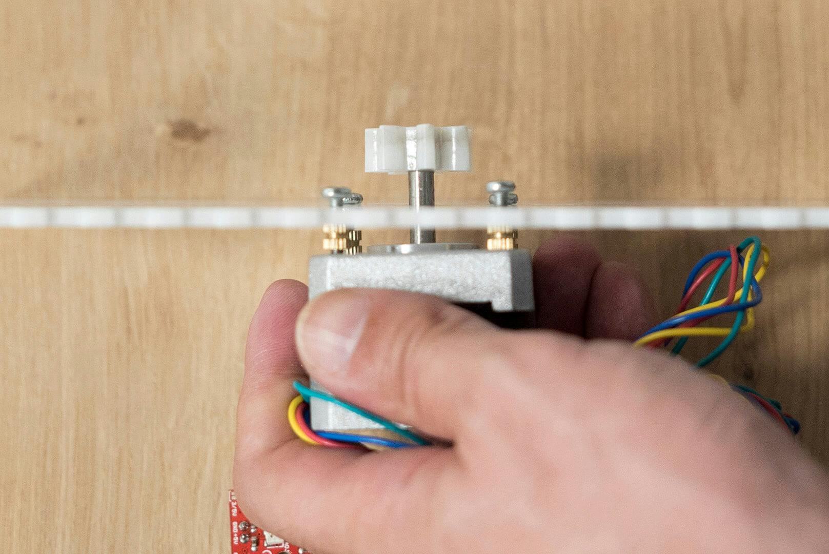
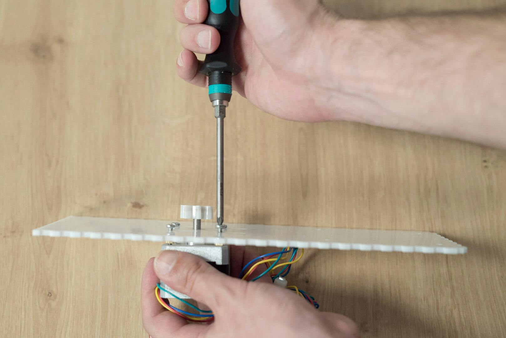
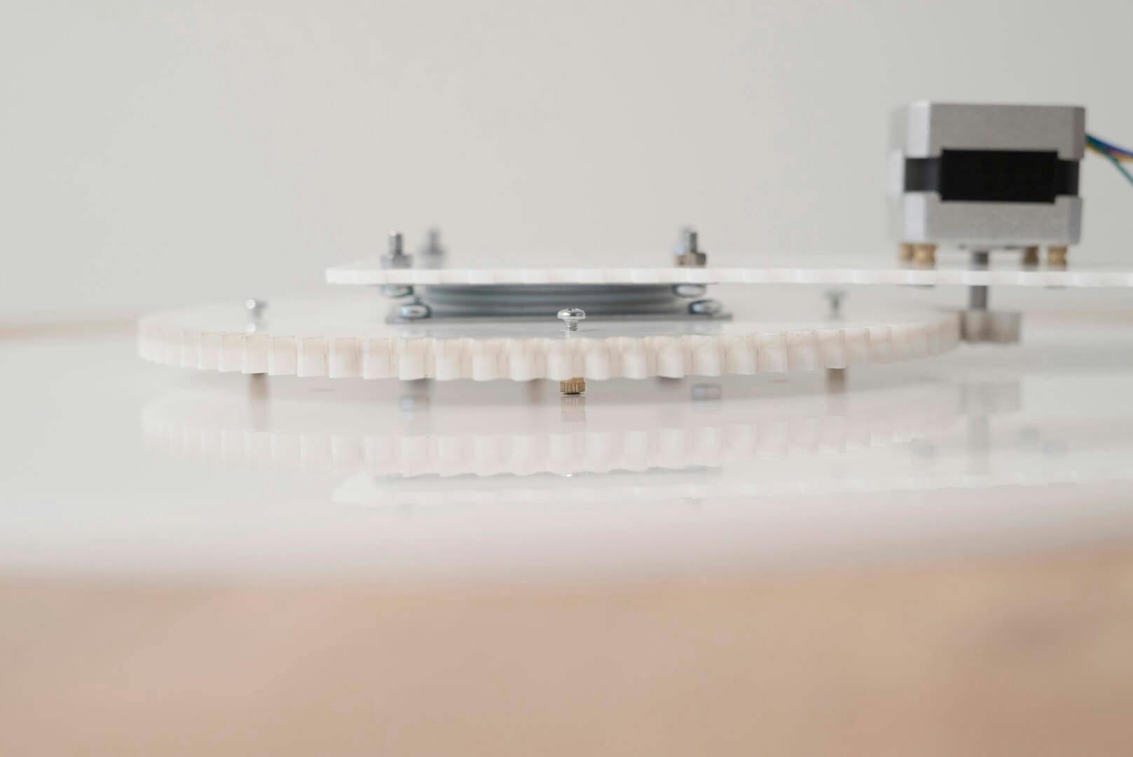
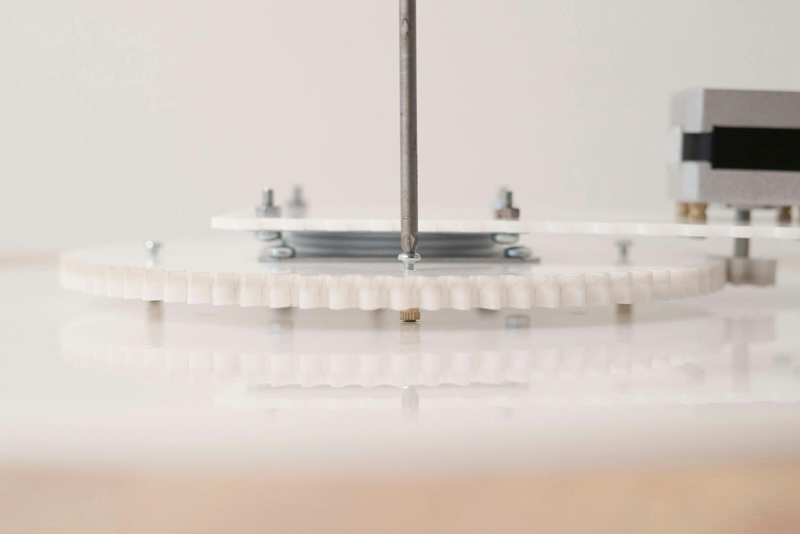
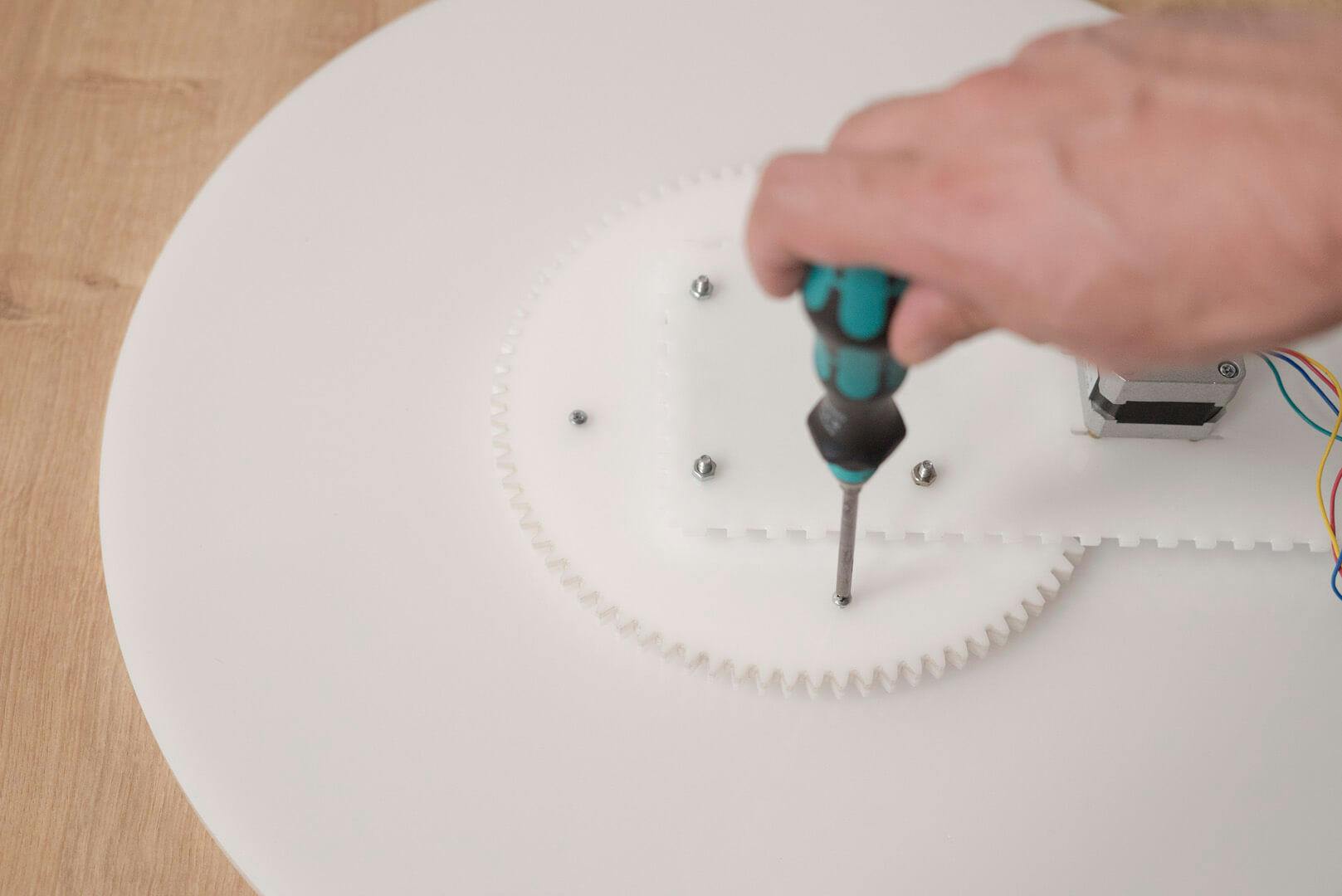
Connect the side walls, the bottom (longer part) and the back wall, and glue it together with acrylic glue or acrylic dissolvent such as methylene chlorideTake a nail and put it through the main hole of the large gear and the main hole of the plate, aligning them on the same axis. Test by spinning the gear.Mark the 4 small holes (M3) on the plate, through the holes in the large gearDrill the 4 holes in the plate according to the markings you made in the previous step with a 4 mm drill, 5 mm deep.Insert the brass threaded inserts into the holes (with m3 screwing)Insert the motor gear into the middle rail of the top Plexi-glass piece, then force the small gear into the motor shaft.Place 4 spacers in between the motor and the top Plexi-glass piece. Screw 4x12mm M3 screws into the motor holes, but don’t tighten, to allow the motor to slip into the rail.Place 4 M4 screws on one side of the Lazy Susan with nutsConnect one side of the Lazy Susan to the top Plexi-glass piece with M4 screws and nutsAlign the Lazy Susan, make sure the screws on both sides are exactly one above the other.Remove the nutsConnect the other side of the Lazy Susan to the large gear using M4 screws and nuts, using needle-nose pliers or locking pliers.Move the motor closer on the rail, bringing together the small and large gears, and tighten the motor screws.Use 16mm M3 screws to connect the large gear to the plate. Place spacers with M3 screwing, 5 mm height.Insert the LCD screen in the front niche of the box.Insert the rotary encoder to its place and super glue it. Connect a knob to the other side ( you can either print one or buy one)Insert the LED into its placeFor quick and easy assembly, we used a Prototype Shield. This allows connecting the components and Arduino comfortably with jumper wires and male headers.Jumper Wire 2-pin - for the IR Led Jumper Wire 4-pin - for the LCDJumper Wire 5-pin - for the Rotary EncoderTo connect the power supply and Arduino we made an extension cord using a DC Barrel Jack Plug - Male and DC Barrel Jack - Panel Mount, soldering wires to ground and VCC between them. We connected the Panel Mount Barrel Jack to the back panel and the male to the Arduino. This way we can connect the power supply to the back wall.Place the plate and motor in the boxingConnect the panel to the front of the boxing.![]()
![]()
![]()
![]()
![]()
![]()
![]()
![]()
![]()
![]()
![]()
![]()
![]()
![]()