NodeMCU - A Perfect Board for IoT
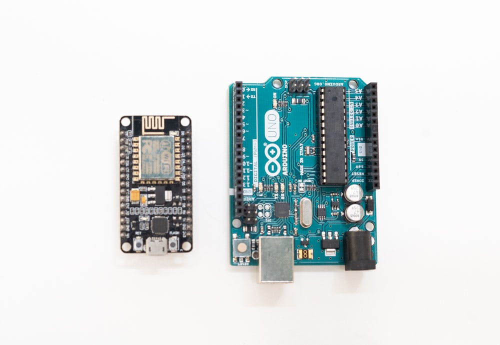
NodeMCU is based on the Esperessif ESP8266-12E WiFi System-On-Chip, loaded with an open-source, Lua-based firmware. it’s perfect for IoT applications, and other situations where wireless connectivity is required. This chip has a great deal in common with the Arduino – they’re both microcontroller-equipped prototyping boards which can be programmed using the Arduino IDE. If you’re familiar with Arduino, using NodeMCU is a logical next step if you’re looking for a more compact, WiFi-equipped alternative.
In this post, we’ll take a look at the nodeMCU pinout, and show you how you can integrate NodeMCU into your next project.

So, why would you choose to use a NodeMCU when the more widely-documented Arduino is around? Well, the NodeMCU has several distinct advantages. Before we detail them, however, we should state that the NodeMCU, technically, isn’t a device, but rather the firmware that loads onto one. In practice, you’ll see the NodeMCU firmware available for sale pre-loaded onto the board. If you already have an ESP8266, all of the connectivity options we’ll run through here will still apply.
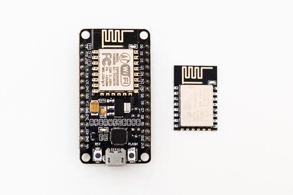
There have been many different ESP modules over the years, each with their own advantages and drawbacks. There have been just two types of NodeMCU boards, however: versions 0.9 and 1.0. The 0.9 version is blue and comes loaded with the ESP-12 chip, while the 1.0 is black, and comes with the ESP-12E (which stands for ‘enhanced’). There are several key differences between the two chips, the most notable being that the later version comes with 22 pins and the earlier one comes with just 16.
Given that the ESP8266 is a more recent release than the Arduino, it’s not surprising that it has stronger specs. There’s a 32-bit RISC processor clocked at 80MHz, along with a generous RAM complement and support for up to 16mb of external flash storage. The device is especially useful for IoT applications, thanks to its tiny footprint and built-in WiFi support.
In all other aspects, however, the ESP is pretty much similar to the Arduino. There’s an on-board voltage regulator that ensures the cleanest possible power to the MCU itself, as well as a push-button reset and a USB connection for easy interface with your computer (as well as serial transmission, which we’ll get to later).
The ESP8266 works with 3.3 volts rather than the 5 used on most Arduino units. To save space, there’s no independent socket for a power supply; rather, the unit is powered via a micro USB cable and provides 3.3 volts to other components via 3 pins evenly spaced around the edge of the unit. There are also 4 pins going to ground. We suggest tethering your 3.3v and ground pins to the outer rails on your breadboard – it’ll make life easier as you design your circuit.
To get the NodeMCU to read an analog voltage, like the one produced by a moisture sensor or a potentiometer, you’ll need to connect the signal to the ADC pin. This pin is connected to a device called an Analog to Digital Converter, which (you’ve guessed it) will turn that analog voltage into a digital value that your microcontroller can make sense of.
ADCs work by placing a row of comparators in series. If the voltage read is higher than a fixed voltage, a one will be output, while if it’s lower, a zero will be output. On the ESP8266, the ADC is 10-bit, which means we have 10 zeros and ones for a total of 1024 possible values. This makes it possible to record precise changes in voltage. For example, we might connect a rotary potentiometer to the 3.3v pin, the ground pin, and the ADC, and then turn the potentiometer to increase or decrease the value.

You might think that having just a single ADC input on the nodeMCU would be a little bit limiting. And you’d be right. But happily, there’s a device that can solve this problem, expanding that single input into eight or more of them. This device is called a Multiplexer (or Mux). When you add the NodeMCU into your circuit on the app alongside multiple analog input devices, a 74hc4051 Mux IC will be added automatically.
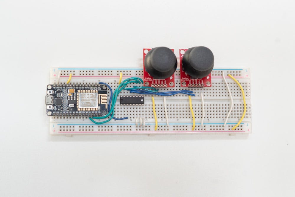
The 74hc4051 is an eight-channel analog multiplexer. It works a lot like an 8-way switch that can be controlled using digital voltages. Thus, you’ll need to generate the appropriate signals on your microcontroller to route the voltages appropriately and then take a reading. So, if you wanted to track 8 potentiometers through a single ADC, you might create a ‘for’ loop in the Arduino IDE to rapidly cycle through the multiplexer’s eight channels, polling each before moving to the next one. So, if you have a control panel of eight separate inputs – say, the sliders on a control surface, you might poll them constantly using your multiplexer and broadcast any altered values.
If you want to go even further, you might chain multiplexers together: one multiplexer might in turn connect to eight more, for a total of 64 inputs.
In such a setup, you would need more control pins, and it would take more time to poll the entire grid – which would make it unsuitable for situations where rapid polling is required. The circuit might also become a little bit bulky– which kind of defeats the purpose of using the ESP8266. If you need to poll many inputs, you’d probably want to use a different board with more ADCs.
The 74hc4051 can also be used as a demultiplexer, which can be used to recover the 8 original signals from a single complex stream of digital information. That’s a little bit trickier; but it’s performed using largely the same principles. Since the 74hc4051 is actually just a fancy switch, it doesn’t matter which way the current flows, and that’s why the same device can do multiplexing and demultiplexing.
However, if you use multiplexing to drive a grid of LED lights,bear in mind that you’ll only be getting an eighth of the effective signal to each of the outputs, and so the effective brightness of your LEDs will be diminished – particularly if you’re using PWM dimming (which we’ll get to in a moment).
Let’s take a look at the pinout of the 74hc4051:
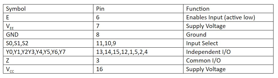
The multiplexer is housed in a 16 pin IC package.
Eight of these pins are used as inputs (or outputs), and they’re routed to the common ‘Z’ pin number 3 depending on the voltages present at the ‘select input’ pins 11, 10 and 9.
You’ll need to supply 3.3-5 volts to the VCC pin, and tie the GND at VEE pins to ground.
The VEE can be provided with a negative voltage, but for most DC circuits we can simply tie it to ground.
To select the input you’d like to read from (y0-y7), you’ll need to generate the appropriate 3-bit binary combination using the “select” pins - s0-s2.
For example, in order to read from pin y5 the combination of the select pins should be s2,s1,s0 = 1,0,1 respectively. Remember that these values are zero-indexed.
If you know your binary code, it shouldn’t be hard to figure out, but there’s a helpful cheat-sheet available in the form of Table 3 of the datasheet.
The Enable pin (6) is active LOW. This means that in order to read from the input ‘Z’ it must be LOW.
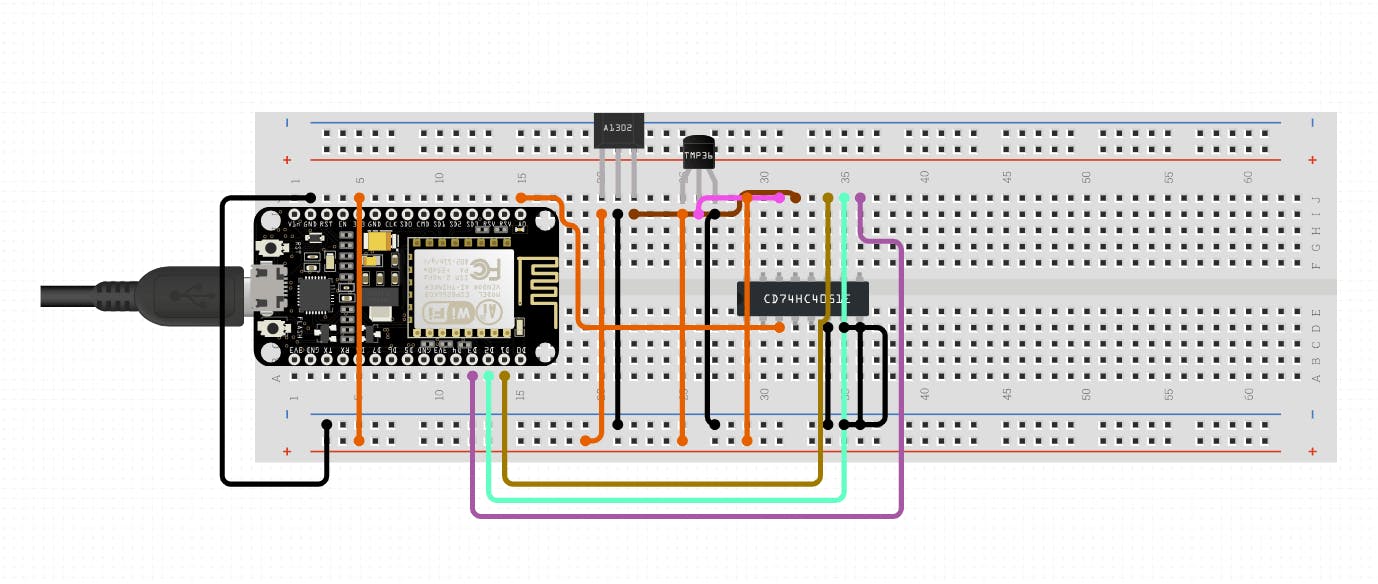
As we said earlier, on circuito.io the multiplexer is added automatically whenever two different devices are connected to the analog input.
For example, if you decide to wire an analog temperature sensor and a hall effect sensor, the multiplexer will appear on the breadboard automatically. The mux behaves just like any other passive devices like resistors and capacitors.

You’ll be using the analogRead() function in order to read values from your analog pin. If you’re using a mux, be sure that you’ve selected the right channel using digitalWrite() commands, and pulled the input active pin low. For best results, we suggest writing a specialized function declaration that changes the digital out pins you’re using to control the multiplexer according to whatever value you input. Adapting the ‘selectMuxPin’ function from Sparkfun’s multiplexer guide is a great starting point.
Once you’re done any necessary routing and issued the analogRead(), you’ll get a digital value between 0 and 1023. It reads between 0v and 3.3v, so be sure that you have the right voltages going into the MCU.
Here’s a pinout diagram of the esp-12e from our friends at Acrobotic. You can compare it to the Arduino pinout which we covered extensively in this post.
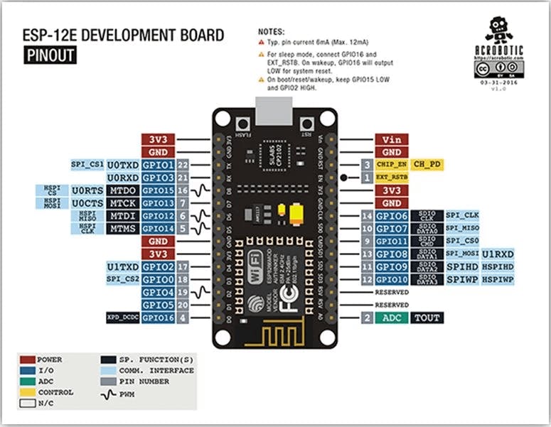
CC-BY pinout diagrams by Cisco at ACROBOTICACROBOTIC
Let's go into a bit more detail about the different pins and communication protocols supported by the NodeMCU:
You’ll notice that some of the digital pins come with Pulse Width Modulation, or PWM, functionality. This provides us with a means of simulating an analog signal using a rapid series of digital pulses. The longer the ‘on’ portion of these cycles, the stronger the signal will appear to be.
So, if you’re turning an LED on and off rapidly, the longer the ‘on’ cycle is, the brighter the LED will appear to be.
PWM signals are also commonly used to control motors – the higher the PWM function, the more power will be transmitted to the motor.
You could do this using any of the digital outputs on the MCU by writing a cycle of code that rapidly cycles a given pin on and off, but this would interfere with the main program and use up valuable resources. A better solution is to use one of the separate PWM outputs, which will take care of all the cycling for you once they’ve received a value.
You can write a value to a PWM using the analogWrite() function. Make sure that you’ve selected a PWM-compatible output. On the NodeMCU, these are D2, D5, D6 and D8.
The NodeMCU supports all three of the main serial communication protocols found on the Arduino (and a range of other MCU-equipped devices). These are:
UART, or Universal Asynchronous Receiver/Transmitter, is a form of serial communication that relies on just one wire going in either direction. Since the format is asynchronous, there’s no need for a clock signal to be sent along a separate cable: the data is simply transmitted at a predetermined rate (the ‘baud’ rate), with the connected devices unpacking the data as it arrives on the other end. On the NodeMCU, UART is done via pins Rx and Tx, which are respectively used to receive and transmit.
Inter-integrated circuit does have a separate clock signal, but uses just one wire for data transmission. It’s great for connecting a single master device to multiple slaves, each of which has a separate address.
I2C is also called ‘TWI’, or ‘two wire interface’. The SCL and SDA pins are on digital pins D1 and D2. As the name implies, I2C is great for connecting integrated circuits to one another.
Our third variety of serial communication is SPI, or ‘serial peripheral interface’. It’s commonly used to connect microcontrollers and other integrated circuits, much like I2C – but it uses three pins rather than just two. It’s also full-duplex, which means that every read operation is able to coincide with a write operation travelling in the other direction. Unlike I2C, only the master device in an SPI chain is able to modify the clockspeed. On the NodeMCU, SPI uses three pins: D5 is the CLK; D6 is the Master In Slave Out (or MISO); D7 is the Master Out Slave In (MOSI).
In Arduino IDE, UART is known simply as ‘serial’. When you’re using it, you’ll be unable to read or write other digital voltages to the RX and TX pins.
You can initiate serial behavior by using the Serial.begin() command, where the baud rate sits in between the brackets. You’ll need to match the baud rate between devices, or they’ll be unable to speak with one another.
In certain protocols, such as MIDI, all devices must adhere to a predefined baud rate shared across an entire industry. So, if you’re using your NodeMCU to trigger notes on a synthesizer, you’ll be using a baud rate of 31250bps.
You’ll then be able to use a range of commands designed for this sort of serial communication. If you’re using UART to receive data, we highly recommend using the Arduino IDE’s serial monitor, which you’ll find under the tools menu.
Make sure that you’ve set the baud rate to one you’re using, and you’ll be able to see incoming serial events coming in in ASCII text. This makes troubleshooting more straightforward.
The other forms of serial communication are a little more complicated. To use I2c, for example, you’ll need to use wire.h in your sketch. This library allows you to easily communicate with compatible devices.
Bear in mind that there’s only a 32-byte buffer in the library, so any transmissions larger than this won’t be properly sent. Every bit beyond the buffer will be cut off, resulting in a stream of incomprehensible data. For many applications, this isn’t much of a problem; if you really need to send lots of data, then work out an elegant way to break it down into smaller chunks, and send them one after the other.
Finally, let’s consider SPI. This protocol is designed for connection to multiple devices, and incorporates 3 wires common to every device in the chain, and an additional ‘slave select’ connection unique to each slave device. By pulling a slave device’s SS pin low, you’ll instruct it to send and receive information along the other 3 wires. To use SPI, you’ll want to download the Arduino IDE’s SPI library.
External interrupts eliminate the need for us to poll a given digital pin regularly; when the relevant signal changes, a special set of instructions will be triggered. This means we can cut repeated ‘digitalRead()’ commands out of our code entirely. It also allows the microcontroller to respond virtually instantaneously, rather than waiting a cycle for the polling to take place.
Each of the pins on the ESP8266 can be setup to receive external interrupts, with the exception of GPIO 16.
If you’re familiar with interrupts on the Arduino, then you’ll find implementing them on the ESP 12-E just as straightforward. You’ll be using a piece of code called an Interrupt Service Routine. Whenever the pin changes, this code will be executed before the program returns to the main loop. As such, it’s worth making your ISRs as concise as possible. Sticking a huge nested ‘for’ loop in there is likely to cause a noticeable delay.
Pin 3 allows us to reset the circuit using an external signal. It’s perfect if you want to create a hard reset button for your circuit in situations where the one on-board isn’t suitable (such as if you’re housing the device within a purpose-built enclosure, or if you’d like to reset it from several metres away). It also allows you to send reset signals from another microcontroller, which might be convenient in more complex projects.
To reset the circuit, you’ll need to pull this pin low. Therefore, we’d suggest pairing your reset switch with a pull-up resistor to eliminate the possibility of floating voltages resetting your ESP at seemingly random intervals.
The fact that NodeMCU can be reprogrammed using the Arduino IDE makes it especially convenient. But before you can get started, you’ll need to first configure the IDE to recognize the new board.
Let’s run through the process:
1. Open Arduino IDE and navigate to file -> preferences
2. In the space marked “additional Boards Manager URLs” add the following url: http://arduino.esp8266.com/stable/package_esp8266com_index.jso
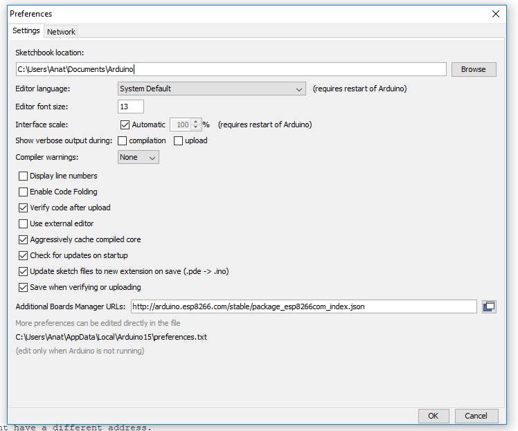
3. Click “OK”
4. Navigate to the Boards Manager. You’ll find it under Tools>Board>Boards Manager.
5. Type “ESP8266” into the resulting search bar. Then install the package.
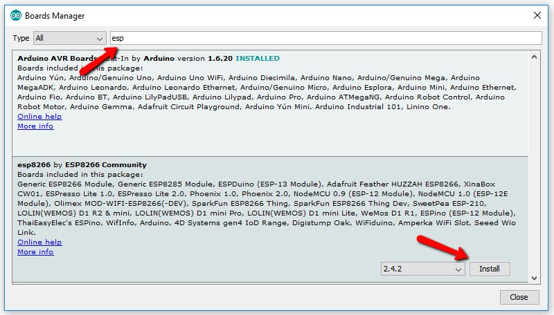
6. Select the exact model. Go to Tools>Board and select “NodeMCU1.0 (ESP-12E module).”
You’re now ready to start uploading code to your ESP, and take advantage of all the great connectivity features we’ve been through!
Have any comments or questions? You're more than welcome to share them with us on the dedicated thread on our forum.